What's new

Constrain Multiple faces

beastro

Senior Member
Good evening,

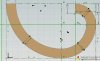
I have to tangent constrain a surface that is composed of a Fibonacci sequence. Screenshots attached.
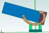
The Bearing has to move over its entire length tangental to the supports. However, the problem is that the bearing surface is segmented in 3 faces since it has to be constructed in the sketch as 3 different arches. Doing it with a spline is not an option, as it has to be exact and I found no way to constrain a spline to a sketch figure.
In the assembly, I can only constrain either face without loosing freedom of motion.
  • Is there any way to fuse many faces into a single face?
  • Any trick to make this work?
Thanks and kind regards

Berthold
 

Attachments

  • Screenshot 2020-09-25 215903.jpg
    Screenshot 2020-09-25 215903.jpg
    728.8 KB · Views: 37
  • Screenshot 2020-09-25 215736.jpg
    Screenshot 2020-09-25 215736.jpg
    113.6 KB · Views: 38

HaroldL

Alibre Super User
I found no way to constrain a spline to a sketch figure
If you create the sketch with Reference Figures (arcs) then overlay the Spline on those figures. You'll need to zoom way in and add quite a few more nodes to the spline to get it to follow the arcs as close as possible. Once extruded you'll have a continuous surface on the part.

SplineOverlaidonRefSketchFigures.png

But that won't help you any because Alibre will not allow a tangent constraint to that surface anyway. Now someone at Alibre must know that applying a tangent constraint to a spline derived surface is going to come up more than once in a while given the number of mechanisms designed that use cams.
 

Attachments

  • ConstrSketch-SplineOverlay.AD_PRT
    356 KB · Views: 2
Last edited:

idslk

Alibre Super User
as it has to be exact
Hello Berthold,

for which purpose it has to be exact? Do you want to be able to move it freely with the mouse?
Do you want to do some kind of collision check with it?
There might be a way to make it happen with some math and an additional "movement element" like in this script.

Regards
Stefan
 

NateLiquidGravity

Alibre Super User
A long time ago I made something like this work. You couldn't make things tangent to spline surfaces then either. I believe I needed to create a point using the spline edge and an axis of contactor travel. That point became the contact location and updated when the part moved. Then I constrained the other part to that point.
 

idslk

Alibre Super User
spline edge
Nate,
there is no "spline" edge in Bertholds design, there are 4 radii with tangents at their connecting points -> some kind of polyline -> no polyline contraint.
For the travel along a spline i have posted a video some times ago...
Regards
Stefan
 

idslk

Alibre Super User
nearly indistinguishable
hm, from Bertholds homepage :
Telescope making, Optics and Astronomy
He is not designing country roads :D even if they should take you home and not to nowhere;)
Regards
Stefan

for lew from AlibreScript help:

upload_2020-9-26_18-4-40.png
 

idslk

Alibre Super User
Lew, if you find your things, it will be ok, as long as you let me find mine...
I can read and so i can see, that there is polyline support in Alibre in various manner. What is missing is some kind of "polyline" constraint.
May you try to read and understand the information...
upload_2020-9-26_22-24-19.png
There is a Table of contents (Inhalt), an index (Index) as well as a search function (which non of my analog books has!) and you can set your own bookmarks (Favoriten). If you are willing, you get usefull information from there. I have used the help often.

Regards
Stefan
 
Lew, if you find your things, it will be ok, as long as you let me find mine...
Hi Stfan -- The last time Alibre documentation can, in my estimation, be said to be worthwhile was the Alibre Design V12 User Guide. Information on such things as "The Hole Preset System" disappeared when real manuals did. -- Lew
 

beastro

Senior Member
If you create the sketch with Reference Figures (arcs) then overlay the Spline on those figures. You'll need to zoom way in and add quite a few more nodes to the spline to get it to follow the arcs as close as possible. Once extruded you'll have a continuous surface on the part.

View attachment 31660

But that won't help you any because Alibre will not allow a tangent constraint to that surface anyway. Now someone at Alibre must know that applying a tangent constraint to a spline derived surface is going to come up more than once in a while given the number of mechanisms designed that use cams.

Hi Harold,

Yes, I found that out the hard way, before posting my question. My single biggest request after using Alibre for the past 10+ years is to get more constraining options.
 

idslk

Alibre Super User
real manuals
That was at the time when we were drawing with ink on parchment paper?
As well as i like books, i also like digital information and something is better than nothing.
Do you have something usefull to help Berthold?
Regards
Stefan
 

beastro

Senior Member
A long time ago I made something like this work. You couldn't make things tangent to spline surfaces then either. I believe I needed to create a point using the spline edge and an axis of contactor travel. That point became the contact location and updated when the part moved. Then I constrained the other part to that point.
I remember something like that many years ago. I was designing some supports for my lathe and had to add some limited movement to the assembly. It worked by making a remote geometry and hiding it.
I was thinking about something similar, but couldn't find a way..
 

beastro

Senior Member
Hello Berthold,

for which purpose it has to be exact? Do you want to be able to move it freely with the mouse?
Do you want to do some kind of collision check with it?
There might be a way to make it happen with some math and an additional "movement element" like in this script.

Regards
Stefan
Actually, the precision is needed because the part has to be parametric and has to be built lateron. A spline is useless for me for that purpose, unless I print it on paper and trace it on the part to be cut.
The constraining would be useful for being able to simulate different radii and orientations. I did it the poor mans way now and just created different sets of constraints for the faces and activate/supress them manually as I check the movement.
 

beastro

Senior Member
hm, from Bertholds homepage :
Telescope making, Optics and Astronomy
He is not designing country roads :D even if they should take you home and not to nowhere;)

Oh my... that page is in desperate need of updating. Half the content does not even load anymore on modern browsers and Google refuses since a long time to even index it. I have even thought of taking it down alltogether for the moment..

So, my conclusion to this is for the moment: I'll print a 3d model of the thing with different shapes and sizes of bearings and figure it out the old fashion way following in the footsteps of Gaudi when he planned the statics of Sagrada Familia with a tiny model and little sandbags as weights.
 

NateLiquidGravity

Alibre Super User
I did it the poor mans way now and just created different sets of constraints for the faces and activate/supress them manually as I check the movement.
This actually leads me back to a brilliant idea I started a while back. I've made a script that is run in the background as you move the assembly - when one "helper ball" part intersects with another "helper ball" they are used to trigger things. It could trigger a parts color, a constraint, a configuration, or even assembly movements. In this case one "helper ball" would be at the contact zone and other balls would be at the ends of each arc. Then as each intersect they could be used to trigger OFF one set of constraints and ON another set of constraints. Thoughts?
 

beastro

Senior Member
This actually leads me back to a brilliant idea I started a while back. I've made a script that is run in the background as you move the assembly - when one "helper ball" part intersects with another "helper ball" they are used to trigger things. It could trigger a parts color, a constraint, a configuration, or even assembly movements. In this case one "helper ball" would be at the contact zone and other balls would be at the ends of each arc. Then as each intersect they could be used to trigger OFF one set of constraints and ON another set of constraints. Thoughts?

I think this is an absolute brillant idea!!
 
That was at the time when we were drawing with ink on parchment paper?
As well as i like books, i also like digital information and something is better than nothing.
Do you have something usefull to help Berthold?
No I do not as the concept of User's Manuals along with Indices and functional Tables of Content have been done away with as well as the concepts of grammar and Language. It is like unto Giov attempting to perform traditional Lofting using "tools" that were created by those entirely unfamiliar with the traditions and techniques developed over the (approximately) one-and-a-half centuries that said practice and experience developed. And yes, I started out Drafting using a ruling pen on linen. I was also a member of the team that "qualified" the Gerber Interactive Design System to NASA and NAS operational requirements. -- Lew
 
Top