What's new

Constrain Obrong holes help

rgyuka

Member
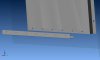
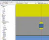
Is there some way to constrain the 'center' point of a vertical and horizontal obrong hole?
If there both vertical or horizontal I have no problem (selecting inner radii faces), but I have no idea how to do this, if even possible?

I'm using V11.1 and attached the original assembly & Sheet metal parts as well.
I'm trying to get away from ACAD for our booth designs and Alibre seems to handle everything except this.
Any suggestions would be much appreciated.
 

Attachments

  • Obrong-align.jpg
    Obrong-align.jpg
    74.4 KB · Views: 107
  • Obrong-align.zip
    382 KB · Views: 96

NateLiquidGravity

Alibre Super User
This is the easiest way I can think of perhaps this will work for you: when making the sketches of the slots go Sketch > Insert > Axis and put an axis in the center. Then when constraining the parts right click on the parts and Show Reference Geometry. Then mate the axises. I'm away from my Alibre install so this is all just from my memory.
 

Ralf

Alibre Super User
Hi Rudy,

I recommend to insert a plane in the middle/center of the Obrong.
Then you can follow Nates step:
Then when constraining the parts right click on the parts and Show Reference Geometry.
Please have a look:
 

Attachments

  • Tie_panel-41.zip
    396.7 KB · Views: 105
  • Plane2.jpg
    Plane2.jpg
    187.6 KB · Views: 103
  • Plane1.jpg
    Plane1.jpg
    285.5 KB · Views: 114

rgyuka

Member
Ah... I knew there would be a way!

Thank you, Nate & Ralf.

Oh by the way Nate, I love that GA2DEC program you wrote, great addition!
 

rgyuka

Member
Ralf/Nate, I'm sure I'm missing something simple here but I can get 'some' of what you both say to work, not all of it anyways.
-I can insert a plane/centered/parallel to the 'long' side by selecting the (2) half circle-radii.

Ralf, how did you get the plane centered vertically on a horizontal obrong?. Mine always goes to the center of one or the other half circle? I got it to work by using (2) planes, 2nd offset from the 1st.

Nate, do I need to use some reference line to get the Axis dead-center of the obrong? I could not figure this one out.

I got it to work using edges as well, but not very elegant and a lot of extra steps.

Any further insight would help.
 

Ralf

Alibre Super User
Hi Rudy,
Please download my example.
 

Attachments

  • Example-download.jpg
    Example-download.jpg
    17.7 KB · Views: 1,092

cherkey

Senior Member
Or you could use Tangent Constraint using the inside arc of one obround to the flat inside of the other obround, offset by half the obround center to center. This would not update if the obrounds change, like it would if you constrain using the centered planes, but if the obround sizes are fixed this'll do ya.
 

Attachments

  • slotconstraint.JPG
    slotconstraint.JPG
    31 KB · Views: 95

Leno

Member
The Obrong´s were created with the stupid ACAD 2D Shape function.
Therefore, it is difficult to move/change them later.
 

NateLiquidGravity

Alibre Super User
rgyuka said:
Nate, do I need to use some reference line to get the Axis dead-center of the obrong? I could not figure this one out.

This depends on how they were made. If you use the Obround Shape tool then it is easy to get the center. Otherwise you will need to make reference lines.
 

Attachments

  • obround.PNG
    obround.PNG
    54.3 KB · Views: 95

rgyuka

Member
Thank you All!

This 'thick' Canadian sometimes has a hard time seeing the tree, through the forest, but you have shed some light!

Thanks Ralf, I was hoping to get away from Math & 3D measurements, but I understand your ways now!

Never would have thought of that technique, thanks Cherkey!

Nate, I wish I could make your 'axis' through the Obrong center work but man, I must be dense....
Yes, I did use the 'Obrong' feature tool in sheet metal, but as soon as I try and insert an 'axis', the center point 'disappears ' and I can only select the 'perimeter'. I tried after the cut hole feature, before cutting the hole, to no avail.
I even tried to do it as a 'part', as in your example (mine were in sheet metal) and I still could not get it to work?

If you have time and would not mind uploading a 'sample' drawing on how you did this, I would be extremely grateful!.

Though I have got it too work (tediously), I would like to learn this technique and simplify matters.

I really do appreciate the effort and time you forum members take to help newbie's such as myself, far better than any tutorials!
 

NateLiquidGravity

Alibre Super User
I think the problem you are having is one that got all of us at one time or another. The only way to insert an axix in a sketch it is in the Sketch menu: Sketch > Insert > Axis. This is different then just going: Insert > Axis. (Insert > Axis is the same as the icon on the toolbar).

See my attached image for the correct menu to use.

As I said this trips up most of us before we learn it. The two different ways should be merged for the program to determine if you are in a sketch or not.
 

Attachments

  • Sketch Insert Axis.PNG
    Sketch Insert Axis.PNG
    52.5 KB · Views: 92

rgyuka

Member
Thanks for clearing that up Nate, I assumed (incorrectly) the Icon on the toolbar was the same.
I see using your method; single point selection creates a perpendicular axis to the normal plane and a (2) point selection creates it normal to the plane, dead center!

This is exactly what I needed, thanks again.
 

indesign

Alibre Super User
I think this is designed to work like this for ease of use. But it does make it unclear to users as how to do this. I think Nate is correct and this function is difficult to discover.

Imagine a very complex solid with pages of sketches in the design tree. Click the icon and every vertex in every sketch appears on the screen. It would be very difficult to find the ones you need. But wouldn't we all like to have the ability to use sketch features in many places? So this limited use axis/point insert for sketches is for our ease of use even though it is difficult to discover since most people just would try to click the icon. Not sure how long it was before I figured out that they functioned sepperately.
 

NateLiquidGravity

Alibre Super User
I didn't mean it that way exactly. I was thinking more that they would combine the two kinds of functions into one button/menu so that when you press the button instead of exiting the sketch that you are editing it uses the function of the in sketch one. IDK its still kinda confusing. :roll:
 
Top