What's new

Controlling digits in hole callouts

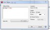
What property in Alibre drawings controls how many digits are displayed for my hole diameters in hole callouts?

It appears that it uses the "Default" dimension style and there is no way to force it to use another dimension style for callouts?

I have a drawing with only a few reamed holes that need to be called out to 4 digits. I really don't want to have to change the default precision to 4 digits and apply a new style to every other dimension in the drawing just to pick up these few holes.

Edit:
The other problem with this is that it applies the 4 digit style to the DEPTH of the callout as well and I actually only want a 2 digit precision on the depth. I hate to have to do these manually. Argh.
 

Ralf

Alibre Super User
Hi vandewallede,

In what standard/norm (ANSY, JIS, ISO, DIN...) you have to deliver your 2D drawings?

I ask, because if you have real dimensions with more than 2, 3, 4...digits like: 1.5684
you cannot cut it, to 2 digits, because such dimensions are wrong.

If you have a dimension with: 1.5600, you can use: Zero Suppression -> Leading and/or Trailing
 
The complaint here is truly valid. Let us consider the case of a pilot hole for tapping. The diameter of the hole in inches would normally be a 3-place decimal dimension. The depth of the hole would normally be a 2-place decimal dimension. General tolerances assigned by the number of decimal places would then provide the specific tolerances for manufacture. A dimension style would apply the decimal precision to all the components of the dimension.

Whereas my personal respect for Ralf is huge (I cannot tell you how many of Ralf's posts have helped me), this is a case where his training is misleading him because of the difference between inch-based standards and metric standards. In the (adopted in 1984) ISO standards, general tolerances are applied to feature types. I.E. My general tolerances note would define default tolerances by: edge to edge type dimensions, edge to center-of-hole type dimensions, center-of-hole to center-of-hole type dimensions, hole-diameter dimensions, hole-depth dimensions, etc. In the inch-based world, general tolerances are applied based on the number of decimal places used -- I.E. a dimension given as .X will have a specific +/- tolerance, a dimension given as .XX will have a specific +/- tolerance, etc. Such values are provided for angles as well as distances. This is one of the inherent faults of the CAD system conventions adopted in 1994.

The problem here is that, in the inch-based conventions, hole diameter X depth and chamfer-distance X angle dimension often require separate decimal precision. There is no easy way to establish such difference within a dimension style settings as they current sit. This argues for a new dimension style type or a complete rewrite of the ANSI/ASME specification set...
 

Ralf

Alibre Super User
this is a case where his training is misleading him because of the difference between inch-based standards and metric standards
Lew,

All my points are valid, independent of any standard/norm...
For specific requirements, I had asked a question. Do you notice that?

Hi vandewallede,

In what standard/norm (ANSY, JIS, ISO, DIN...) you have to deliver your 2D drawings?

I ask, because if you have real dimensions with more than 2, 3, 4...digits like: 1.5684
you cannot cut it, to 2 digits, because such dimensions are wrong.

If you have a dimension with: 1.5600, you can use: Zero Suppression -> Leading and/or Trailing

If I create a 3D part with defined dimensions, Hole -> Depth-Condition, and/or Thread-Series, Thread-Type, Thread-Lenght ...
and derive a 2D drawing from this 3D Part, and get dimensions e.g : 1.5684 -> I cannot cut 4 digits to 2 digits, because the dimension/value is wrong. (rounded...)

The better/right way is to use real/valid/standardized... dimensions, Hole -> Depth-Condition, and/or Thread-Series, Thread-Type, Thread-Lenght in 3D Parts,
so it is not necessary to edit/cut real Dimensions/Digits subsequently in 2D Drawings.
 
Ralf,

I hear what you are saying, but I still beg to differ. In American (inch-based) traditional standard drafting practice, the depth of a hole always defaults to the point of the drill. If you need it dimensioned to the flank of the drill, that needs to be specifically dimensioned as such. However, in nearly all instances (the exception proving the rule) the tolerance on a drilled hole's depth is nowhere nearly as precise as its diameter. I understand completely that the German (mm-based) traditional standard (and now ISO standard) practice is to display all the relevant dimension's decimal places and use feature-based tolerance notes to define the applicable tolerances.

Confounding this further are the numerous industry-specific traditional standards that are not in compliance with ASME/ANSI standards as well as government agency specific standards. Most American draftsman use Dr & Tap 1/4-20 X .50 as their callout for a hole that is defined (under FED-STD-H28) as being properly called out as .2500-20UNC-2B (Deep Symbol) .50. The second callout type is the legally correct callout for work being done for the government or regulated industries. The first callout type is traditionally sufficient in many industries. In certain rare instances, the formally correct callout would be (two lines): ø.201 (Deep Symbol) .80 (second line) .2500-20UNC-2B (deep symbol) .50. In even rarer instances (i.e. critical areas of spacecraft or aircraft in my experience) the ø.201 value would have a specific tolerance applied to it -- something I have only seen a few times in my life.

Specific to blind hole tapping, you will find the equations that calculate the optimum minimum tap drill (pilot hole) depth in my paper Pilot_Hole_Considerations posted at http://www.scribd.com/Lew%20Merrick (and, although written using inches, apply to metric units as well). The calculated value is calculated such that more decimal places than necessary apply to the resultant.

My point is that Alibre needs to be flexible enough in definitions of dimension styles to accommodate such variations...
 

rogpf44

Senior Member
Lew,
I have a question as to your following statement.

"In American (inch-based) traditional standard drafting practice, the depth of a hole always defaults to the point of the drill. If you need it dimensioned to the flank of the drill, that needs to be specifically dimensioned as such."

I have always been instructed that hole depth is the specific diameter called out and not to the point. If it is important that the hole not break thru for example, you would call out “Point Depth” at the end of the dimension, or dimension to the point on the drawing.
For example, if you called out a hole, .250 to a depth of .50, this means a hole is needed at that diameter for a depth of .50.

I am self taught and I am not trying to change your mind or challenge what you are saying, I am just asking for my knowledge

Thank you.
 

kdevoe

Senior Member
I have to agree with rogpf44, in an inch-based system (USA) the depth of the drill hole does not include the point. In all my years working, fisrt as a tool maker and now a designer I have never encountered a situation where the drill point was included as part of the specified depth.

Kevin
 
Kevin & Rog,

I was actually a member of one of the ANSI committees that went through definitions for the Y14.x specification set from 1981 through 1994. One of the reasons I resigned was that they were allowing people with no background in drafting or manufacturing to create new terms that were unfounded in the traditions of design or manufacturing and apply them willy-nilly to the standards. Another was that people being appointed did not bother to read the history of standards and then make "suggestions" for them.

True Position Dimensioning and Feature Control Tolerancing came out of systems developed by the military and NACA/NASA in the 1950's. Specific to use of the drill point as the controlling dimension for a drilled depth is the (early-1960's) commentary in the ANSI notes establishing the problems in determining a drilled hole's flank location whereas a simple pointed depth gage can find the point's depth. This is supported by notes (supplied by Cleveland Twist Drill) noting that, when setting up a drilling operation, picking up the point of the drill bit was simple, but finding the actual flank position is more complicated and open to error. (The data package supplied by Cleveland Twist Drill to ANSI for the preliminary release of Y14.5 is an amazing document that provides more information on drilling and tapping than most people even know exists! My copy has deteriorated badly as it was mid-1970's photocopy of a early- or mid-1960's typed and hand illustrated set of pages.)

Now, the interesting thing is that the section in which such information was defined under ANSI Y14.5M-1994(R2004) has been removed from ASME/ANSI Y14.5-2009 and now refers you to ASME/ANSI Y14.100-2004(R2009) (Engineering Drawing Practices which contains no information on dimensioning or tolerancing) which, in turn, references to the superseded version of Y14.5M-1994 and Y14.5.1M-1994 for greater detail. Can you say, Circular firing squad?

The thing is that the 1994 release of Dimensioning & Tolerancing was the last one I worked on. I sat in a meeting with a bunch of PhD types who would not know where the web of a drill was (much less how to relieve it) and pulled out the Cleveland Twist Drill documents as part of a several hour screaming match over the mathematical theory of tolerancing principles (which was finally released as a supplement under ANSI Y14.5.1M-1994). This was the last time the Y14 series was released as an ANSI document (they are now all officially ASME documents -- and ASME addresses mail to me as Mr. PE apparently having no idea what a Registered & Licensed Professional Engineer is).

The worst part to all of this is that a drilled hole is not, under any condition, a precision hole! Truly precise holes are made with other tools. The argument was (and still is) a complete waste of time...
 

MikeHenry

Alibre Super User
Was the original question ever answered?

One of my current parts has a reamed hole and I want it called out to 4 decimals, but there seems to be no way of changing the number of significant digits in a hole callout other than the manually edit the diameter value in the dimension. That seems like a good way to bite yourself in the butt should the hole spec ever change.

Mike
 
MikeHenry said:
Was the original question ever answered?

One of my current parts has a reamed hole and I want it called out to 4 decimals, but there seems to be no way of changing the number of significant digits in a hole callout other than the manually edit the diameter value in the dimension. That seems like a good way to bite yourself in the butt should the hole spec ever change.
Mike,

What you need to do is to create a 4-place dim STYLE that you can apply to the dimension in question. I have a rather long set of dimensioning styles defined with my drawing border format. They are: 2-place-std, 3-place-std, 4-place-std, 2-place-plus-minus, 2-place-plus-minus, 4-place-plus-minus, as well as other more obscure ones. They are part of the values that, IMO, should be able to be saved and loaded separately from the drawing form.
 

MikeHenry

Alibre Super User
Hi Lew,

I'm using the actual hole callout dialog (not a standard dimension) and there seems to be no way to specify a user-created style for the callout format of the hole. Are you suggesting that I use a standard dimension instead of the hole callout?

Mike
 

Attachments

  • Hole Callout Dialog.JPG
    Hole Callout Dialog.JPG
    30 KB · Views: 8
Mike,

I am completely unfamiliar with that dialog. I make no attempt to pass through dimensioning from the model to the drawing. The (ASME/ANSI Y14.1/14.100) standard default is to "thru" (which is a company specific modification and not part of the formal standards) with the deep symbol modifier when that is not true. Such things get my design work "bounced" -- so I use nothing that creates such non-standard dimensioning.

In point of fact, my model defaults to 4-place decimal dimensioning whereas my drawing defaults to 3-place decimals. I then use Styles to make any changes.

One of the "points" I constantly make to people learning CAD is the difference between design dimensions and manufacturing/inspection dimensions. One of the things that I do that drives many people out of what's left of their minds is the design using Maximum Material Condition (MMC) and use Unbalanced tolerances only. If I do that, any deviation from MMC merely acts to assure a proper fit-up.

???
 

MikeHenry

Alibre Super User
Looks like the best thing to do with detailed dimensions like this is to just delete the standard hole callout dimension and create a new dimension with the standard GM dimensioning tool. The "THRU" spec has to be added by hand, but maybe that can be created as a custom dimension style, which I'll try later.

Sorry for the thread drift , but does Unbalanced Tolerance refer to a callout like "1.000 +0.002 -0.005" or something else. If I understand Maximum Material Condition that refers to the maximum dimension a part or component can be expected to exhibit.

Mike
 
Mike,

An unbalanced (a U with a circle around it) tolerance is +X/-Y based on the dimension's value. If one is working to MMC, the the tolerance is always +0/-X or +X/-0 in form. A (say) rectangular body at MMC would be constructed at the dimension+tolerance value. The "tolerance" would then be +0/-(2*tolerance). A (say) circular hole would be constructed at MMC would be constructed at the dimension-tolerance value. The "tolerance" would then be +(2*tolerance)/-0. (Not counting the MMC modifier to the tolerance.)

Whereas I do realize that many shops never see this format of tolerance (and most do not even know how to truly apply True Position Dimensioning), my argument is that, if I tell the person in the shop where "perfect" lies, they have better odds of delivering parts & assemblies that have better functional fit-up. It is like unto (the now officially discarded) practice of providing interpart coordination notes to assume that the person in the shop understands what feature set is going to create the critical fit-up at the assembly level. These are part of the reason that I quit the ANSI committee work on such things I spent more than a decade doing.
 
Following on about MMC and TP call outs. How do I apply a boxed co-ordinate such as those shown in ASMEY14.5-2009 Fig 7-5

The only (very poor) way I could figure it out was to dimension as usual, remove the dimension and insert a boxed note where the dimension was. Not good.
The print I am working on is attached for reference.

Thanks
 

Attachments

  • Capture.JPG
    Capture.JPG
    32.5 KB · Views: 25
  • TP Example.pdf
    58.1 KB · Views: 19

DavidJ

Administrator
Staff member
No - that isn't an existing option. Submit a support request - that should at least make sure it is logged.

[EDIT - see Ralf's post later - it is possible and is already included , my mistake ]
 
Hayden,

I am not sure where you got your "examples," but it was not out of the ASME/ANSI Y14.5-2009 specification. THRU is the default assumption unless modified with a DEEP symbol. (Similarly, and often overlooked, a leading zero in a value indicates that it is metric just as trailing zeros indicate that it is inch-based.)

The problem is that GMD (like most CAD systems today) is not truly compatible with the international standards for dimensioning & tolerancing that derive from ANSI Y14.5-1969 (the original incarnation). DATUM B, for example, should have the datum flag replace the opposite value arrowhead in the ø3.250 callout. Similarly, the ability to define a value as BASIC should be inherent in all annotation operands and it is not. The correct designation for your 90° BSC angular dimension should be: 3X 90° BSC (=270° BSC). And the correct designation for your 4X ø.514 +.001/-.002 ON A ø7.250 BASE CIRCLE dimension should be 4X ø.514 +.001/-.002 ON A ø7.250 BSC BASE CIRCLE (where BSC should be identified by a BASIC BOX modifier).

My proposal, currently implemented in General CADD (a 2D only CAD package), is to make use of the vertical bar (|) character as a (if you will) boxing toggle such that text surrounded by vertical bars becomes "boxed" as defined under the appropriate ASME/ANSI or ISO specification. I know of no other use for this character in general design/drafting. In this approach, the BASE CIRCLE value would be entered as: ON A |ø7.250| BC and be displayed with a Basic Box about the ø7.250 value.

The issue of associating DATUMS with dimensions (such as your DATUM B callout) is somewhat more difficult. It is something that is a problem for virtually all CAD packages today and requires a great deal more though than has been given to this problem to date.

Final comments: Your DATUM C and DATUM D callouts default to title block tolerances for (implied) squareness to each other and the initial DATUM A. I would imagine that you really want to hold them closer than +/-.005 and +/-1° in relative form. Also, your Section A-A is located as a First Angle Projection condition even though your title block proclaims Third Angle Projection. (As somebody who learned his drafting from an old (First Angle Projection) German, this is a mistake I have never once made, right?)
 

Ralf

Alibre Super User
Hi guys,

Are you discussing about such a "box" ?
.
 

Attachments

  • Basic-Box.png
    Basic-Box.png
    6.7 KB · Views: 254
Top