What's new

Correct method to generate a sheet part (question)

TimB

Member
Hi and thanks for the great help given in the past, I hope you can help me again.


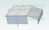
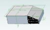
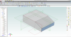
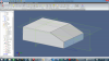
I want to make a part using the sheet metal tools. I have attached the solid version that I want to replicate. and my attempt at the sheet part. However I'm stuck as you will see on how to fill in a missing section.

Any pointers appreciated


Many thanks

Tim
 

Attachments

  • NC outer case.AD_PRT
    312 KB · Views: 7
  • NC outer case Sheet attempt.AD_SMP
    580 KB · Views: 11
  • NC outer case missing element.JPG
    NC outer case missing element.JPG
    28.6 KB · Views: 3
Tim,

I don't have time to dig into your SMT part at this instant, but the rhombic shaped closure has to be an extension of the side bent flange of the part rather than the top angled flange. The only question in (what's left of) my mind is how you want to make the attachment between the rhombic side flange extension and the other to mating parts. I would ass-u-me that you would make a tab flange that would bend to the inside of the top angled flange and the (attached) end flange.

You will, almost certainly, have to create some kind of slot or tear at the intersection of the side bent flange and the tab flange extending from the rhombic extension to the side bent flange to make the (connecting) tab flange work out nicely. Which way you orient the slot or tear will depend upon the equipment used to make the bends.
 

TimB

Member
Hi Lew_Merrick

I really appreciate the time you put in to this.

Some more info


As you can see from the photo this is the section I need to add to the drawing. The arrows indicate the welded edges. This is very similar to a product I sell 100's off. The sheet metal company did the original drawing based of a 2d drawing I did many years ago. I want to keep up with the times so am trying to use the sheet tools in Geomagic design.

Your assessment of what needs to be done is what I see is needed to but its the "How to do it" bit that is eluding me.

Anyway many thanks for your time so far.

Tim
 

Attachments

  • NC outer case missing element_edit2.jpg
    NC outer case missing element_edit2.jpg
    32.9 KB · Views: 3
Hi

Hope this helps. I have to manually cut free the corners in Solid and then converted to sheet metal.
At the moment I only have the V17 Beta Version of GM, so even the Step.
 

Attachments

  • NC outer case.AD_PKG
    184.2 KB · Views: 1
  • NC outer case.stp
    132.1 KB · Views: 2
Hi Tim,

Here is a really rough start on the solution for you...
 

Attachments

  • NC outer case Sheet attempt LM Mod.AD_SMP
    599 KB · Views: 6

Jim C

Senior Member
Tim,

You can add a flange to the end of the side section to extend over the area of interest and then trim as desired. The only "trick" that I have found is that the sheetmetal flange routine does not like a zero degree bend so use something like 0.01 degree and it is happy.

Jim C
 

Attachments

  • NC outer case-1.AD_SMP
    710 KB · Views: 1
  • NC Outer-1.PNG
    NC Outer-1.PNG
    218.1 KB · Views: 8

Jim C

Senior Member
Tim,

Just had a second thought before going to the shop. You can change Flange3 to a single flange using just Edge<20> and then use a width offset of -96mm. That gives you a single flange of the proper length. Unfortunately if you try that for both sides at the same time the opposite flange gets extended in the wrong direction. (A mirror operation would be nice to have.). Do the same thing for the opposite side and then make a shetch for the desired cut and a single "through all" will trim both sides.

By the way, that looks like a nice equipment cabinet.

Jim C
 
Jim C said:
You can add a flange to the end of the side section to extend over the area of interest and then trim as desired. The only "trick" that I have found is that the sheetmetal flange routine does not like a zero degree bend so use something like 0.01 degree and it is happy.
Try a Tab.
 

HaroldL

Alibre Super User
Tim,
No sure if there is a "Correct" method for making sheet metal parts. I look at it as the best method for the part being modeled.
That being said, here is method that uses the Lofted Flange to define the angled shape. The side flanges are trimmed up with the Closed Corner and trimmed to fit. The side flanges are made equal length via the Equation Editor.
This is a v16 format, if you can't open it I posted an image of the sketch. The values are approximate.
 

Attachments

  • NC Outercase Example.png
    NC Outercase Example.png
    260 KB · Views: 7
  • NC OuterCase Example.AD_SMP
    715 KB · Views: 10
  • lofted flange sketch.PNG
    lofted flange sketch.PNG
    11.7 KB · Views: 171
Top