What's new

creating a cylinder with dimensions dependent upon another

Jasper

Member
I am trying to create a cylindrical “child” part based on the dimensions of another cylindrical “parent” part (e.g., two axles, or a bushing and an axle, etc). Specifically, I want both the diameter and the extruded length of the parent to dictate the same dimensions on the child.

I have read that the Global Parameters functionality cannot access the parameters/values of existing parts, so using Global Parameters is out since the parent part already exists and it would be non-trivial to recreate it. Likewise it seems like it would be a PITA to recreate for spreadsheet-driven design.

Is there a way to use Project to Sketch to achieve this (by creating the child part in an assembly with the parent, for example)? So far I can get Project To Sketch to drive the diameter, but not the length.

Thanks,
PJ
 

DavidJ

Administrator
Staff member
I can think of 3 ways;-

1) As you describe, build an assembly, use project to sketch to create an inter-design constraint. Check carefully if things update when you expect.

2) Create a global parameter file, then go back and edit the original file do that the key dimension(s) follow the global parameter(s). If unsure about this, make a 'Save As' copy of original file first so you have a route back.

3) If Spreadsheet driven design is working on your versions of Windows/Excel, link the dimensions to a spreadsheet.
 

Jasper

Member
DavidJ said:
1) As you describe, build an assembly, use project to sketch to create an inter-design constraint. Check carefully if things update when you expect.

I've been unable to come up with a workflow that passes both diameter and length from one sketch to another. I'm hoping someone can show me what I'm missing. I've only gotten project to sketch to pass one or the other, not both.

DavidJ said:
2) Create a global parameter file, then go back and edit the original file do that the key dimension(s) follow the global parameter(s). If unsure about this, make a 'Save As' copy of original file first so you have a route back.

This is a great suggestion thank you. I didn't grasp that I would only have to re-create the few critical dimensions. If I can't learn a way to do this with project to sketch, I will go this route.
 

Jasper

Member
PJasper said:
I've been unable to come up with a workflow that passes both diameter and length from one sketch to another.

To be more precise, I should've said, "...from one PART to the sketch of another part"
 

DavidJ

Administrator
Staff member
PJasper said:
This is a great suggestion thank you. I didn't grasp that I would only have to re-create the few critical dimensions. If I can't learn a way to do this with project to sketch, I will go this route.

You shouldn't even have to re-create, just link to the global parameter file using equation editor, then edit the existing parameter to equal the global one.
 

bigseb

Alibre Super User
Alternatively (if possible... not sure what else is in your design):

Open new part. Save as cylinder two. Boolean unite cylinder one. Now cylinder two is linked to cylinder one.
 

lamar

Senior Member
I use the Global parameters all the time in parts and assembles to take one dim. from one part to another.
I believe it would also be possible in your case. do you have an example file that you could upload so we could have a look at it. :)
 

TylerDurden

Alibre Super User
DavidJ said:
You shouldn't even have to re-create, just link to the global parameter file using equation editor, then edit the existing parameter to equal the global one.
I'd phrase it this way: Create the global file with the needed parameters and link it to the two parts, then replace the existing parameters in the parts' equation editors with the global's. Done.

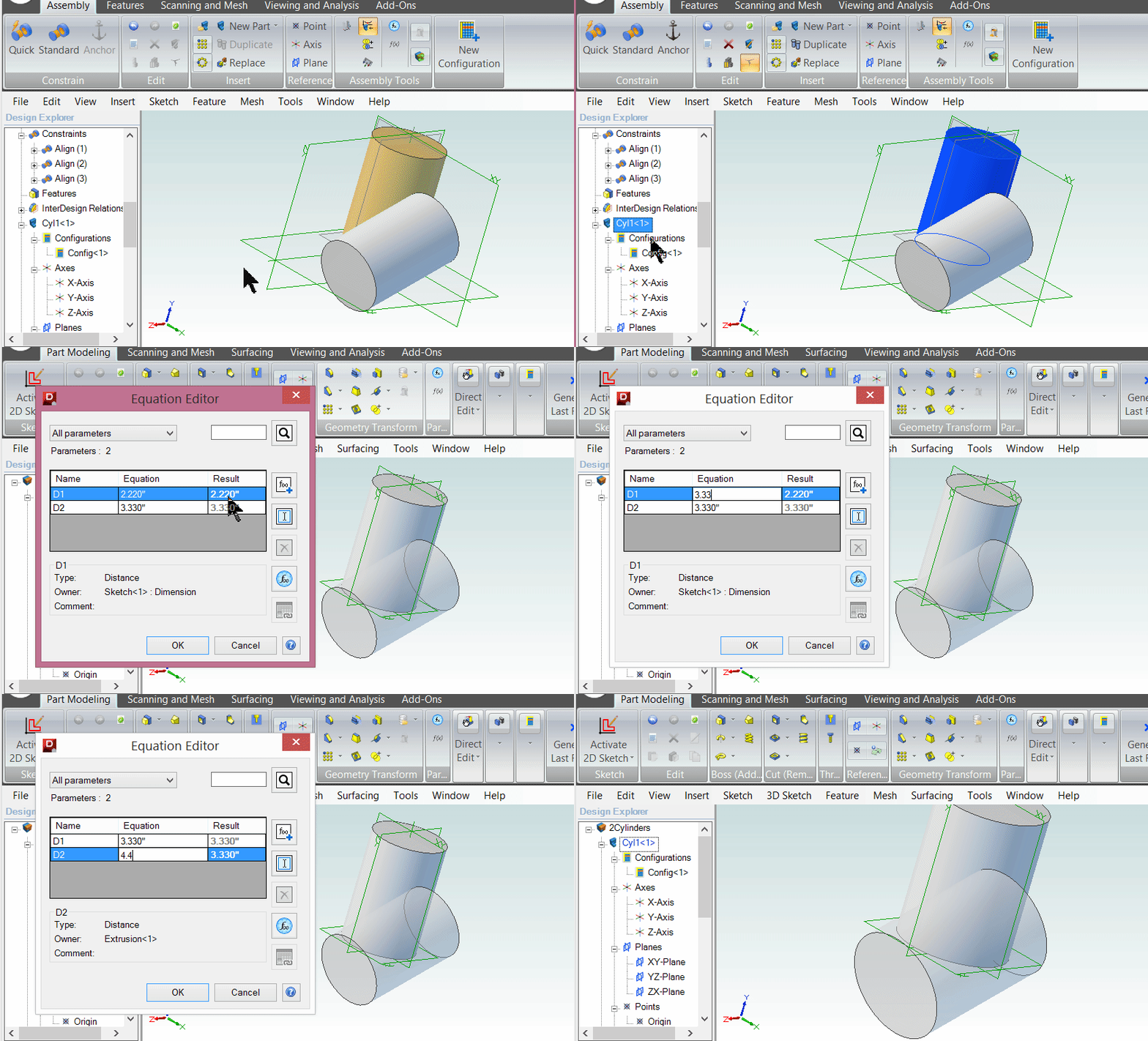
It can also be done with just P-T-S, by making dimensions/parameters a reference sketch in the new part with a projected side view of the first. See attached package.
2016-10-04_09-34-29.gif
 

Attachments

  • 2Cylinders.AD_PKG
    52.2 KB · Views: 2
PJasper said:
I have read that the Global Parameters functionality cannot access the parameters/values of existing parts, so using Global Parameters is out since the parent part already exists and it would be non-trivial to recreate it. Likewise it seems like it would be a PITA to recreate for spreadsheet-driven design.

Is there a way to use Project to Sketch to achieve this (by creating the child part in an assembly with the parent, for example)? So far I can get Project To Sketch to drive the diameter, but not the length.
PJ,

I admit that one of my complaints about Global Parameter functionality is the lack of a (if you will) Global Parameter X's value is "sourced" from Part Y's Equation Editor value Y. However, that can be overcome through planning. The fact is that Global Parameters (say) a_Cylinder_Dia and a_Cylinder_Length can be used within the local Part Equation Editor to generate the relationship between the diameter and length of (Part) Cylinder A and Cylinder B. Granted, doing a Save As and Renaming all the affected files to create another Part/Assembly set is a PITA, but it is a PITA rather than a Problem. Update Designs (<Ctrl>+<Shift>+U) implements any changes automagically.
 

Jasper

Member
TylerDurden said:
It can also be done with just P-T-S, by making dimensions/parameters a reference sketch in the new part with a projected side view of the first. See attached package.
[/quote]

Yes! This is exactly what I was trying to do, but couldn't get it to work for some reason. Why did you put the Cyl1 side view P-T-S edges (or faces?) in their own sketch for Cyl2, rather than the sketch for the cylinder extrusion (sketch3)?

I put everything in the same sketch, and it wouldn't update the length, only the diameter. I will try again your way.
 

TylerDurden

Alibre Super User
If
PJasper said:
Why did you put the Cyl1 side view P-T-S edges (or faces?) in their own sketch for Cyl2, rather than the sketch for the cylinder extrusion (sketch3)?
If you project to an off-square plane, the resulting sketch figures will be foreshortened (similar to a shadow) and the dimensions of those figures will not represent the actual lengths of the geometry .
 

Jasper

Member
TylerDurden said:
If
PJasper said:
Why did you put the Cyl1 side view P-T-S edges (or faces?) in their own sketch for Cyl2, rather than the sketch for the cylinder extrusion (sketch3)?
If you project to an off-square plane, the resulting sketch figures will be foreshortened (similar to a shadow) and the dimensions of those figures will not represent the actual lengths of the geometry .

hmmm...mine were orthogonal and they didn't work. Will try again later today and post the results.
 

Jasper

Member
PJasper said:
TylerDurden said:
If
PJasper said:
Why did you put the Cyl1 side view P-T-S edges (or faces?) in their own sketch for Cyl2, rather than the sketch for the cylinder extrusion (sketch3)?
If you project to an off-square plane, the resulting sketch figures will be foreshortened (similar to a shadow) and the dimensions of those figures will not represent the actual lengths of the geometry .

hmmm...mine were orthogonal and they didn't work. Will try again later today and post the results.

OK So I think I have it working based on your example Tyler. Actually I think maybe it was always working: it appears that any changes don't get propagated through to the child part unless I go in and actually edit the relevant child part sketch. I did not know that. I just assumed that when I opened the assembly with an updated parent part, that those changes would automatically be updated in all the parts of the assembly. that does not appear to be the case.

Does this make sense/is this what you more experienced users would expect?
 

TylerDurden

Alibre Super User
Huh... I was expecting it would update upon opening too!

If I re-connect them by opening the sketch, THEN the second part updated with EDIT HERE on the first part. :-\

I'm a couple of versions behind, so maybe some other members can chime in. Maybe that has been fixed.
 
Top