What's new

Creating multiple parts from one sketch

Nick Lumb

Member
A Solid Edge using friend has suggested a design method to me that creates multiple parts from different bits of the same sketch. To my knowledge Alibre does not allow this - am I correct? If not, how do we do it?

What would be the best way to solve this problem in Alibre? The same friend has to make a nozzle for the outlet of a rocket from three different materials but each following a different part of the same curve. He would draw the curve, divide it into three parts with the cross section appropriate to each material, and then select each cross section individually to create a revolve boss part for each material.

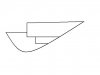
Here is the sketch for the three parts:
 

Attachments

  • sketch.JPG
    sketch.JPG
    8.3 KB · Views: 1,484

DavidJ

Administrator
Staff member
Draw the sketch - save as catalogue feature, then call it up from library and trim as required for each part.

Could maybe also make a 'master template' part - then design all other parts in an assembly context by using 'project to sketch' - this might be very versatile if the associativity was maintained.

There may be other ways to achieve what you require.
 

JJHawg

Member
I'm pretty new to Alibre, but I would consider drawing the complete part on a "base" sketch, and use the "project to sketch" function to copy the parts you want to three new separate sketches. I suppose copy-paste would be about the same.

I don't think there is any linkage between the "base" and "upper" sketches, so you would have to manually transfer changes up the line, but something like this may help...

I have just started playing with "configurations", but I don't see right off how that would help your situation. However, this might be one path to pursue.
 

MilesH

Alibre Super User
JJHawg said:
I don't think there is any linkage between the "base" and "upper" sketches, so you would have to manually transfer changes up the line, but something like this may help...

If you check the option, in the Project to Sketch dialogue box, Associativity will be maintained between your "template Part" and your "real Parts". At present, you'll need to do this in Assembly to get the colour differentiation.
 

Nick Lumb

Member
NateLiqGrav said:

I have created the required assembly using the techniques described in this article: namely, make an outline part that includes all of the final assembly, create one copy for each required part, edit each part in turn to chop out the bits you don't need in that part. Assembling the parts together again is quite fun and the result is as you would expect. However, making changes to, say, that original curve means starting again from the begining: not what I had in mind.

I then tried to create all the parts in the same way but as configurations in order to gain associativity; ie. edit my original outline part to directly alter my final assembly. Unfortunately, configurations don't work like this and altering the sketch the first time destroys the outline part even though it is fully locked.

Miles suggested checking the 'maintain associativity' option when using project to sketch but I can't see how to use 'project to sketch' in this case.

What am I missing?
 

aeromorrison

Senior Member
Multiple features from a single sketch are not supported. Allowing this would be a significant enhancement to the product. The kinds of operations that you describe are much more common than most realize--especially for revolved solids. The single sketch approach is very efficient. I have submitted this item in various enhancement requests to Alibre over the past couple of years. The workarounds mentioned do emulate the desired functionality, but each of them has associativity problems when things start getting complicated. From what I understand about how Alibre works "under the hood" this may be a pretty big (costly) change, though.
 

NateLiquidGravity

Alibre Super User
The simplest solution would be access to other parts reference geometry while editing in an assembly. Although an assembly level sketch would work better for the user.
 

MilesH

Alibre Super User
Sorry, I thought this would work, but it doesn't :roll:
 

Attachments

  • N.L. Example.stp
    173.1 KB · Views: 112

NateLiquidGravity

Alibre Super User
Alex Franke's 'Parameter Wizard' added in with the article I linked might be enough to work for now. Unfortunately the site is broken and the program used for v10 errors in v11.
 

warburton1

Senior Member
There is a way to do this unfortunately I cannot access the forum from my Alibre computer in order to upload the solution file.

It does utilize a single sketch, well almost in that it is one sketch and five or six parameters to control planes. Other than that the big thing here is an intermediary modelling (read Part) step between the assy and the Master geometry model. The intermediary part utilizes basic shapes from the master geometry part to boolean into the required part shapes. These intermediary models are fully contextually linked to the master geometry, thereby any change at the master geometry level is reflected in the top assembly.

If someone could pm me with their email I could pass it along for them to upload to the board until such time as Alibre and I can figure out the problem I am having with the board.
 

warburton1

Senior Member
Here is the assembly model of the linked / contextual modelled nozzle. Hope its useful.

Regards,

Gary
 

Attachments

  • Nozzle_Assy.stp
    334.8 KB · Views: 111
Top