What's new

Cube corner shaped recess in block

IMK

Member
Hello,

What I need is a block or base of say 75x75x15 mm with a recess or hole cut in it that is the shape of the corner of a cube of say 30mm.
The bottom corner of the cube is 5mm above the bottom of the block or base. The line from the cubes top corner to the cubes bottom corner is angled so it points to the centre of the earth.
I hope this make sense.

So how would I go about designing this please?

Many thanks IMK
 

IMK

Member
ASP said:
something like that
Hello ASP,

That great and just what I need but I can't open the "Part.stp" in Alibree Design 11.2 free version... Sorry but should have made that clear.
So how would I go about designing it please.
Many thanks IMK
 

ASP

Senior Member
1. create a sketch on top face of base, and "project to sketch" this face (with maintenance)
2. create reference-diagonals and insert a point at intersection - this is the middle of the base
3. close sketch
4. open sketch again and choose 2D-Sketch - Insert - Axis and select the mid-point created before
5. on one of the sides create a sketch and project that face
6. in the middle sketch a reference-line and insert a point on that with 5mm from bottom line
7. close that sketch and re-open it
8. choose 2D-Sketch - Insert - Axis and select the point created before - this defines the depth
9. insert a plane with the last created axis and the horizontal plane on an angle of (acos(1/SQRT(3)) ~ 54,7334°
10. activate sketch on that plane
11. sketch a horizontal reference line from origin (origin is on the last axis created)
12. project as reference the first created (middle) axis
13. sketch the square with the lower corner at the intersection of these 2 ref. lines
14. Extrude Cut
15. finished :mrgreen:
 

Attachments

  • Unbenannt.jpg
    Unbenannt.jpg
    327.5 KB · Views: 61

IMK

Member
ASP said:
1. create a sketch on top face of base, and "project to sketch" this face (with maintenance)
2. create reference-diagonals and insert a point at intersection - this is the middle of the base
3. close sketch
4. open sketch again and choose 2D-Sketch - Insert - Axis and select the mid-point created before
5. on one of the sides create a sketch and project that face
6. in the middle sketch a reference-line and insert a point on that with 5mm from bottom line
7. close that sketch and re-open it
8. choose 2D-Sketch - Insert - Axis and select the point created before - this defines the depth
9. insert a plane with the last created axis and the horizontal plane on an angle of (acos(1/SQRT(3)) ~ 54,7334°
10. activate sketch on that plane
11. sketch a horizontal reference line from origin (origin is on the last axis created)
12. project as reference the first created (middle) axis
13. sketch the square with the lower corner at the intersection of these 2 ref. lines
14. Extrude Cut
15. finished :mrgreen:

Hello Christian, many many thanks for the explanation.
However you lost me on step 2.
You see I only use Alibre once or twice a year to do simple pocketing jobs as I am real novice at it.
So as this is a quick job I am going to shop to buy plaster of paris to make what I need rather than try to figure out Albre. (Time is Money)
Again many thanks for your help.
IMK
PS I hope Alibre 12 is easier than 11....
 

ASP

Senior Member
this was a simple exercise - but a bit hard to describe in words ( especially in a foreign language)
 

DavidJ

Administrator
Staff member
As always - there are alternative approaches which can be used. Whichever works for you is fine.

If I couldn't be bothered with working out the angles/distances I would instead.

1. Model a cube of desired size, insert an axis through 2 diagonally opposite vertices. This axis will be used later to orient the cube.

2. Model the base, I'd ensure it was symmetric about one axis. Then do a boolean subtract using the cube made earlier as the 'tool' - I'd align the axis inserted in the cube with the axis that the base is symmetric about (running vertically through its centre). That just leaves settign the depth that the cube sinks into the base - another align constraint between bottom face of base and the lowest corner of the cube (offset 5mm).

There are probably a host of ways the detail of this task could be performed...
 

IMK

Member
ASP said:
this was a simple exercise - but a bit hard to describe in words ( especially in a foreign language)

Hello Christian,

Please please do not think I was questioning how you approached this problem as I am sure it is a trivial job for someone who is familiar with Alibre. But for me I find Alibre a real struggle at times. Something have come really easy. I can do simple round and rectangular pockets a have created some nice surfaces and profiles of surfaces etc. But what I really struggle at are planes that have been rotated relative to other object. (To cut a long story short it took almost two hours of reading the help files to create a plane that was inclined to another plane.) Maybe it is me and I just have a blind spot for some Alibre concepts. By the way you English is just fine and something to be proud of…. Probably better than mine.

Again many thanks for you input IMK
 

IMK

Member
DavidJ said:
As always - there are alternative approaches which can be used. Whichever works for you is fine.

If I couldn't be bothered with working out the angles/distances I would instead.

1. Model a cube of desired size, insert an axis through 2 diagonally opposite vertices. This axis will be used later to orient the cube.

2. Model the base, I'd ensure it was symmetric about one axis. Then do a boolean subtract using the cube made earlier as the 'tool' - I'd align the axis inserted in the cube with the axis that the base is symmetric about (running vertically through its centre). That just leaves settign the depth that the cube sinks into the base - another align constraint between bottom face of base and the lowest corner of the cube (offset 5mm).

There are probably a host of ways the detail of this task could be performed...

Hello David,

Well after some seven hours of reading and trying there is NO WAY that this cube can be rotated relative to the base. Sorry but some software houses need to figure out one thing. And that is the cost of owning there products! Not the cost of buying it. But how much your time waste trying to figure how to use… Now I think I speak with some qualification on this matter having written software for forty years. The application I just completed took me three years to write, the user manual was ten pages and I taught six customers in 30 minutes how to use it.

Think I’ll take to my workshop tomorrow and make what I need by hand as it will be much quicker than trying to draw it.

This Alibre stuff I think the most difficult and quirky application I have ever (tried) to use. Can’t afford it anymore…

IMK
 

Attachments

  • CubeRotation.JPG
    CubeRotation.JPG
    100.4 KB · Views: 59

HaroldL

Alibre Super User
DavidJ said:
As always - there are alternative approaches which can be used....
Point in fact, you could also use a Loft Cut. Can you tell the difference between the two methods in the attached image?

IMK said:
...You see I only use Alibre once or twice a year to do simple pocketing jobs as I am real novice at it....
:shock:
IMK said:
...This Alibre stuff I think the most difficult and quirky application I have ever (tried) to use. Can’t afford it anymore…

IMK

IMK,
There ain't no "Easy" button, you need to use any software more than "once or twice a year" to get to the point of understanding how it works let alone becoming proficient with it. As you use it you can learn different ways to achieve the same results.
 

Attachments

  • Triangular Pockets.jpg
    Triangular Pockets.jpg
    24.4 KB · Views: 44
  • pocketed plate.stp
    927 KB · Views: 24

DavidJ

Administrator
Staff member
IMK - perhaps I should have said more explictily that in my suggested method the cube and the base are totally separate parts (each modeled in own workspace) . They are brought together to produce the boolean subtract - the same tools as used in assembly mode allow placement of the cube, including rotation.
 

IMK

Member
Hello DavidJ,

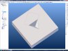
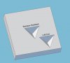
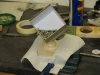
So I am sorry if I was not explicit in my requirement but please find photo IMG_2626.JPG of what I wanted to create. (A simple jig to hold a tri-axial accelerometer while measuring cross axis misalignment)

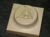
So I simply ran out of play time with Alibre with respect on how to put a cube corner shape indentation in a surface and just made it up using wood filler and a cube (box) to make an impression. I guess this is similar to what you tried to explain to do in Alibre. However I find defining, positioning and moving planes and axis in Alibre really tricky and highly time consuming. Especially when you have made a learning mistake use the undo/redo function and Alibre either crashes or just locks up. It seems that Alibre just like to move forward and seems to reward well expert users, but punishes most harshly the novice and inexperienced users like myself.

A good example being a AD_PRT I did a few weeks ago. I took the original broken block and measured it up. Knocked it up in Alibre in a minute or two, produce the NC code and milled a couple out before breakfast.

Likewise the AccelOrientation-2.AD_PRT that I based this project on. A simple one minute design job, two minute NC production, thirty minutes of milling and thirty minutes of filler setting time. Compare this hour of work with the seven hours of trying to do it in Alibre and nothing to show for it other than more hair loss.

However I wonder if you are really using Alibre as my version knows nothing of STP file! Are you sure you are not using SolidWorks? :roll:

Again many thanks for trying to help me but I had to press on my way as getting the job done had some urgency.

All the best IMK
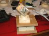
PS How do you like the improvised Sine Table made from large ball bearing and a little more Alibre.
:mrgreen:
 

Attachments

  • IMG_2623.JPG
    IMG_2623.JPG
    898 KB · Views: 53
  • IMG_2626.JPG
    IMG_2626.JPG
    739.2 KB · Views: 51
  • IMG_2627.JPG
    IMG_2627.JPG
    934 KB · Views: 51

DavidJ

Administrator
Staff member
Your original description was fine (unlike some posted here).

If you can't import .stp that Harold posted then I guess you are using the Personal Edition of Alibre.

The .stp is a handy way to 'wrap up together' all the files needed for a design - but PE doesn't support it.

I know what you mean about axes planes etc. - it is initially a lot to get to grips with. I outlined the method I did because it minimised the number of axis insertions required. I added an axis through diagonally opposite corners of my cube in about 15 seconds - Insert -> Axis, select the two corners in turn, click OK.

Probably the best thing to do is work through the built in tutorials, or watch the free subset of the training videos that are available on the Alibre web site - nothing like seeing it done and hearing it explained to really grasp the basics.
 

IMK

Member
Hello Davidj

Re opposite corners of my cube in about 15 seconds - Insert -> Axis, select the two corners in turn, click OK.
Did that easy, but problem is I can't see,find or figure how you now move the cube and or the axis that passes throught it..

Many thanks IMK
 

IMK

Member
Well Guys,
You have all been really helpful here and well if anyone feels like showing me how it is done then mod up my AD_PRT by putting a Cube Corner cut in the top of the post..
Please.... :oops: Many thanks IMK
 

Attachments

  • AccelOrientation-3.AD_PRT
    150 KB · Views: 44

DavidJ

Administrator
Staff member
Try this, not sure if it all works in PE - I had to add a 3D Point on a corner to set the 'penetration depth'.

Hopefully the rest is self explanatory - right click on the cube and select 'show reference geometry' to see the key bits used to align.
 

Attachments

  • Both Parts.zip
    60.3 KB · Views: 46

ASP

Senior Member
for a beginner Davids method is very easy to do (see the videos)
1) create the cube
2) add an axis through it
cube

3) create a boolean substract with that cube
4) and set position of the cube using reference geometries
boolean
 

IMK

Member
DavidJ said:
Try this, not sure if it all works in PE - I had to add a 3D Point on a corner to set the 'penetration depth'.

Hopefully the rest is self explanatory - right click on the cube and select 'show reference geometry' to see the key bits used to align.

Hello David,

Unfortunately the part you posted won't open in my PE 11.2 version, Alibre just throws an exception and tells me to contact support (com.alibre.rose.RoseException: imported file version: 13,0,0,13059 is higher than current Alibre version: 11,2,0,11077) I guess this is due to me having an older versions.

However I changed my AD_PRT and added a cube to the top of the post and put an Axis through it. This I had already figured. The bit that is missing in my skills is how to align the CubeAxis with the system Z axis.

Again many thanks for the help IMK
 

Attachments

  • AccelOrientationWithCube-1.AD_PRT
    173.5 KB · Views: 52

DavidJ

Administrator
Staff member
IMK - you have to model the cube in a SEPARATE part file. You can then use the cube as a 'tool' in the boolean subtract (as shown in Christian's boolean video). There isn't any simple way to move features around within a single part.

You are correct about the files not opening due to version number.

Suggest you also take a look at the user manual with regard to Part Booleans - you can download the PDF manual from your downloads page if you don't already have it.
 
Top