What's new

Cutting 3/4-10 threadded rod Example in Help file has error

tgarson

Member
In the Help file example (Alibre 11.1) for using Hellical cut to create a 3/4"-10 UNC threaded rod, the value used for Minor Diameter is incorrect. The Minor Diameter used to derive H was for internal threads, rather than external threads.

Minor Diameter/2 for the Example should be .315, not .320830.
(I have found that the specification for Minor Diameter External varies from .6273 to .6309, depending on which reference you use.)
H should then be .096, not .086603.
Major Diameter/2 plus .125*H would then be .387.

Maybe I'm nit picking, but that error cost me about an hour of butt scratching as I tried to figure out what I did wrong when the threads did not come out correctly.

Tom G.
 

HaroldL

Alibre Super User
It's no surprise that an error or two may find their way into the tutorials. I found, and submitted to Support, the same concern some time ago when I found a similar "error" in one of the tutorials. The reply from Support was, and I'll paraphrase it here, "...the tutorials are just to show the technique or method to perform a task and NOT to give technical design information. You must always consult with the appropriate Machinery's Handbook or other Technical data when creating your designs."

So, while the turtorial may end up with a "part", realise that they are just taking you through the steps to create it. When you create your design you have to put in your own parameters and not rely on Alibre's tutorials for them, even when they imply a standard part. It should be noted that the tutorial states the thread size as 3/4-10 UNC-3A. Suppose you needed a class 1A or 2A thread or series UNF or 8-UN , wouldn't you search out the correct values for them?

H.
 

tgarson

Member
The problem with this example is that it is pretty poorly documented. The reader is not provided with sufficient information to easily determine the various parameters of the exercise without correlating the values used in the example with the real world item. I was not trying to use the 3/4-10 NC threaded rod. I was trying to follow the example and use the technique to create a 1/2"-20 NF thread.

I am quite aware that mistakes happen. I was pointing out this one so that it might be corrected, thus saving the next fellow some grief, and helping Alibre to look the part of a vendor of a professional product. If you are saying that they did not correct the errors you pointed out to them, then I guess you would be implying that they don't care and I shouldn't bother myself with trying to help them improve their product. I hope that's not the case.

TG.
 

HaroldL

Alibre Super User
Have you submitted this error to Alibre Support? And, if so, what was their reply?

tgarson said:
The problem with this example is that it is pretty poorly documented. The reader is not provided with sufficient information to easily determine the various parameters of the exercise without correlating the values used in the example with the real world item...

I suppose this is the part of the tutorial that you are talking about:

Other than maybe labeling the dimensions, (and using the "correct" values) what information would you like to have included?
So, if you create the sketch as shown in the above illustration, do you get the part shown in the next?

tgarson said:
...I was not trying to use the 3/4-10 NC threaded rod. I was trying to follow the example and use the technique to create a 1/2"-20 NF thread.
So how did your part turn out when you put in the values for the 1/2-20 NF thread?

H.
 

Attachments

  • thread sketch.jpg
    thread sketch.jpg
    55.1 KB · Views: 111
  • thread complete.jpg
    thread complete.jpg
    81.2 KB · Views: 112

indesign

Alibre Super User
Re: Cutting 3/4-10 threaded rod Example in Help file has error

Not to nitpick but I think that is the point of this thread isn't it?

The example clearly states the pitch and it is dimensioned. If the values are off by small amounts to a standard then what difference does it make if you are not using the pitch or dimensions shown.

So is the example just not documented enough due to not reviewing the other tutorials or is there an error that causes the example not to work as described? This is an example not an engineering manual. The tutorial may not be sufficient for a new user to understand. Is this the case?

Like everyone who uses new software I always would like more (and better) documentation and help. Just ask for the help and there are plenty of good users here willing to help.
 

tgarson

Member
As I stated in my first post: The issue is clarity.

If I had used this technique to make threads in an Alibre drawing previously, I would not have needed an example to follow.

The question was not how to select functions in Alibre to create a hellical cut, that's fairly clear. The issue was how to determine what values to use in creating the sketch for making a thread other than 3/4-10. In order to use the example, as is, it is necessary to work backwards from the values given to determine how they arrived at those values, for using a different bolt size/thread. Since the values were wrong for a 3/4-10 thread, I could not do that.

I was able to locate a drawing that shows the geometry of UNC and UNF threads:
http://www.efunda.com/designstandards/s ... thread.git
that provided the necessary additional information I needed in order to calculate the values required for whatever UNC or UNF bolt size/thread I might need, based on commonly available thread specification tables.

Maybe you guys are used to examples that contain data that lead to erroneous results. Maybe it's a cultural thing: "Who cares if its wrong, nobody will build it anyway."
From my perspective, close is OK in a game of horse shoes. Not so in a mechanical drawing. Especially not so in an educational document, which is what we ARE dealing with.

I have not reported this directly to Alibre Support. It''s not a program defect and, now that I know the process, creating threads will not continue to be a procedural problem.

It is my understanding that Alibre personnel monitor these forums, as is the case with the forums provided by the vendors of other softwares that I use. I therefore figured that someone at Alibre would pick this up and put it in the cue to be dealt with at an opportune time. Am I wrong in this assumption?

TG
 

Attachments

  • UNC+UNF Threads.jpg
    UNC+UNF Threads.jpg
    26.5 KB · Views: 104

HaroldL

Alibre Super User
I would not waste my time creating standard threads except for a special case. And I can't think of what that might be. One, it takes a lot of processor horsepower to create the helical feature. Two, standard threads can be handled with the new Cosmetic Thread feature in the model and a callout on the drawing. And Three, just how clear is the thread going to be when it gets printed or plotted in your assembly?
Only for a custom thread design would I go through the effort of making the threads.

tgarson said:
...The question was not how to select functions in Alibre to create a hellical cut, that's fairly clear. The issue was how to determine what values to use in creating the sketch for making a thread other than 3/4-10.
The tutorial does state that the sketch is based upon a pitch of 10tpi and the UNC standard for screw threads. The next step then is to find out what the values are for the thread you need to create.

tgarson said:
In order to use the example, as is, it is necessary to work backwards from the values given to determine how they arrived at those values, for using a different bolt size/thread. Since the values were wrong for a 3/4-10 thread, I could not do that.
They got the values from the UNC thread standard, as stated in the tutorial, and for a different thread you would need that thread's standard.

If I found it necessary to create the thread, the first place I would look would be my Machinery's Handbook to get the values for the thread profile irregardless of what any tutorial had. Not having a copy on the MH at hand it looks like you did the next best thing, i.e. search the Internet.

tgarson said:
I was able to locate a drawing that shows the geometry of UNC and UNF threads:
http://www.efunda.com/designstandards/s ... thread.git

that provided the necessary additional information I needed in order to calculate the values required for whatever UNC or UNF bolt size/thread I might need, based on commonly available thread specification tables.
So, besides the error in the Minor Diameter, if the tutorial had an image like the one you found, would that have given you the info you desired? Except then you would need the table of sizes with all the other pertinent info.

tgarson said:
Maybe you guys are used to examples that contain data that lead to erroneous results. Maybe it's a cultural thing: "Who cares if its wrong, nobody will build it anyway."
From my perspective, close is OK in a game of horse shoes. Not so in a mechanical drawing. Especially not so in an educational document, which is what we ARE dealing with.

Well, they are only examples and no, I wouldn't build an example. I would only look at it for the process to create it. Designers are responsible for their designs, I would never rely on, or use, a tutorial example for my final design creation. That's just way too risky.

And as for an educational document, there are several examples in the text we used in drafting school that had errors. So what's new? (Oh, by the way, your link to efunda.com is broken.) :)

tgarson said:
It is my understanding that Alibre personnel monitor these forums, as is the case with the forums provided by the vendors of other softwares that I use. I therefore figured that someone at Alibre would pick this up and put it in the cue to be dealt with at an opportune time. Am I wrong in this assumption?

Yes, they do monitor the forums and sometimes post. But you should still submit this to Support so it gets properly entered an error.

H.
 

tgarson

Member
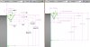
I would have designated the parameters using accepted industry symbols, rather than values, on the Alibre example drawing. Then placed a small lookup table next to it which provided the associated values. Those changes, along with the drawing from efunda.com would have provided sufficient information to correctly follow the example to its conclusion. I'm certain that whoever created the example did so in Alibre and just copied the sketch, complete with dimensions, to the Help document.

Perhaps an Alibre feature that provides the option of creating a parameter lookup table which is associated with symbols used in place of specific dimensions on a drawing would be a desirable feature. I will suggest that to the Alibre folks.

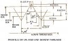
An all inclusive thread table would not be needed, just one containing the information relating to the specified example thread would be sufficient.

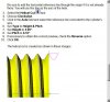
I am already aware of the existence of the Cosmetic Threats function. I appreciate that as an option, however the need for details on any particular drawing can only be determined by the designer, knowing the intended audience.

This particular part is the center piece of a mechanical design and being able to see the threads on it greatly enhances the ability of a viewer, other than the designer (me), to understand the function of the product with a minimum of explanation. Were I drawing something like an entire engine block assembly, I would provide Cosmetic Threads on the various components used along with separate drawings showing examples of the True Threads on each threaded part, other than stock bolts and nuts. The primary goal of any drawing is to clearly illustrate what is expected to those who do not already know. It is neither to glorify the technical expertise of the designer nor perpetuate his/her employment, nor, for most of us, is it purely entertainment. Many years ago, I studied engineering, including mechanical drawing, at Penn State (Nobody had CAD then, not even NASA!). There I learned that a drawing which is logical, straight forward and relatively easy to comprehend by those who may not be engineers is often paramount to the success of any project. Anything less is deficient. If it takes a few extra seconds, or even minutes, to do a redraw, so be it. (Try having to take a week to do the same job by hand.) After all, Alibre is not a video game. Instant gratification is not the most important thing.

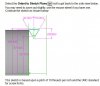
Sorry about the bad drawing link. Here is it again, copied right from my browser:
http://www.efunda.com/designstandards/s ... thread.gif

I will go ahead and report this to Alibre Support.

TG
 

HaroldL

Alibre Super User
tgarson said:
... The Minor Diameter used to derive H was for internal threads, rather than external threads....(I have found that the specification for Minor Diameter External varies from .6273 to .6309, depending on which reference you use.)...
H should then be .096, not .086603.
Major Diameter/2 plus .125*H would then be .387.

Maybe I'm nit picking, but that error cost me about an hour of butt scratching as I tried to figure out what I did wrong when the threads did not come out correctly.

Tom G.

Sorry to nit pick your nit picking, :) but something in your original post has been bugging me. Then, as I went over your explanation, and did a completly dimensioned sketch, it hit me. You state that the Minor Diameter is used to derive H. It can't. H is related the Pitch through the 60 degree angle. ( H=Sin60*P ) So you can't change H from .086603 to .096 without changing the pitch from 10tpi to 9tpi for the example in the tutorial. To paraphrase Star Treks' Scotty "Capt'n, You canno' change the laws of mathematics." :)

I think it would be more correct to say that the Minor Diameter is derived from H.
Granted, the way the sketch is created, a wrong value for the Minor Dia may have been entered. But I don't think you can't get there by changing the value of H.

From info I've been able to find from various internet sources (Wish I had my Machinerys' Handbook available :x ) it looks like the tutorial example is a 3/4-10 UNC-3A thread.

I'm uploading the part file I used for the images. With the equations, different size threaded rods can be made from it by editing the Extrusion diameter in Sketch<1> and the Pitch for the Helical Cut in Sketch<2>. I was able to make a 1/2-20 NF.

After noodling with this for a while I found this http://en.wikipedia.org/wiki/Unified_Thread_Standard which explains it in more detail than I can in right now.

H.
 

Attachments

  • thread sketch dim-equations.jpg
    thread sketch dim-equations.jpg
    90.7 KB · Views: 124
  • EXT THREAD EXAMPLE.AD_PRT
    3.4 MB · Views: 105
Top