You are using an out of date browser. It may not display this or other websites correctly.
You should upgrade or use an alternative browser.
You should upgrade or use an alternative browser.
Diagonal Bends
- Thread starter nvanlaar
- Start date
NateLiquidGravity
Alibre Super User
Do you want it on the model just for rendering purposes? Or just in the drawing?
Are you using the sheet metal part tools in Alibre? (not everyone has them)
If so do you want it to unbend?
Are you using the sheet metal part tools in Alibre? (not everyone has them)
If so do you want it to unbend?
Ralf
Alibre Super User
Nick,
Therefore, this part can be created as a 3D Part.
It is usually a formed sheet metal part -> produced with a deep-drawing press / servo-electrical driven mechanical press......Anyone familar with sheetmetal work will know what I am talking about.
Therefore, this part can be created as a 3D Part.
NateLiquidGravity
Alibre Super User
Where that is not available (in real life) a slight bend each diagonal would work - it has here at least. Regardless of real world methods Ralf is correct that the only way to do so in an Alibre model would be to use the solid part features. However if only required on the drawing two lines on a view constrained to the corners should be fine as well.
nvanlaar
Senior Member
I'm pretty sure it's a set of diagonal breaks that are put into a sheet metal part. They are very shallow and yes, the second break partially flattens the other, but the creases are permanently there since the steel has been stretched at the bends. It's common in ag equipment covers because it stiffens the otherwise floppy large rectangular cover.
First, is there a way to mark it in a drawing (other than manually)?
Second is there a way to create the sheet metal part with sheet metal tools (AD Expert) or am I stuck modeling it as a standard part and then annotating it appropriately?
Thanks everyone,
Nick
First, is there a way to mark it in a drawing (other than manually)?
Second is there a way to create the sheet metal part with sheet metal tools (AD Expert) or am I stuck modeling it as a standard part and then annotating it appropriately?
Thanks everyone,
Nick
HaroldL
Alibre Super User
nvanlaar said:How would you do a pair of diagonal bends used to stiffen a piece of sheetmetal? They are only a few degrees. Anyone familar with sheetmetal work will know what I am talking about.
Thanks for any help,
Nick
Nick,
It's called a Cross Break. And No, it cannot be done in Alibre sheet metal, at least not now, but maybe if they implement formed features in sheet metal.
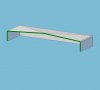
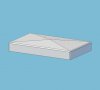
Typically, it is only 1-2 degrees but can be more, depending on how high the peak needs to be. And, at least on the drawings we do at work where we use SolidWorks, it is called out on the drawing as phantom lines drawn diagonally across the part and a leader note indicating the height to the peak in the center, such as: .25 CROSS BREAK. I just finished a design today that had a .62" high cross break on a 74" x 34" panel
If I want the cross break to show in the model then I will create it in the sheet metal part using a forming tool.
In the shop it can be made by bump forming it on a press brake before any other bends are done on the part.
Incidentally, in SolidWorks it can be modeled using a forming tool or in SW2009 inserting a Sheet metal cross break feature. It doesn't change the sheet metal but does show on the drawing as diagonal lines and a call out. Here are a couple of images from SW showing a cross break. In the flattened sheet configuration the formed feature is suppressed so the sheet metal can unfold.
Alibre has some catching up to do so this can be done in Alibre sheet metal too. From what I've seen on the feedback forum, formed features are still "under review". I'm not sure if how to interpret that, does it mean "We're still trying to figure out how to program this stuff". :?
Attachments
HaroldL
Alibre Super User
It would be interesting to see if Inventor can do a cross break, and if it does, what is the work flow.
Because CAD sheet metal cannot form the cross break as it is done in the real world, it has to use other methods to show the feature. SW uses the forming tools to create a solid model feature that must or should be suppressed in the flat pattern.
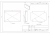
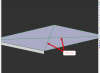
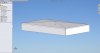
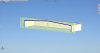
I did some quick modeling in Alibre and came up with a work flow that may be used. To create the cross break part I created a solid model part with a loft feature to simulate the cross break. I then filleted and shelled the part, then added some extrude cuts to simulate the closed corners. I also made a sheet metal part with the same dimensions. In the assembly model you could have a configuration showing the solid model part with the cross break and another configuration with the sheet metal part.
On the sheet metal drawing diagonal lines are drawn then changed to the Bend Centers layer. A notation is added calling out the cross break. Another method would be to sketch the pitch of the cross break in a side view and add a dimension with a note for the cross break.
Because CAD sheet metal cannot form the cross break as it is done in the real world, it has to use other methods to show the feature. SW uses the forming tools to create a solid model feature that must or should be suppressed in the flat pattern.
I did some quick modeling in Alibre and came up with a work flow that may be used. To create the cross break part I created a solid model part with a loft feature to simulate the cross break. I then filleted and shelled the part, then added some extrude cuts to simulate the closed corners. I also made a sheet metal part with the same dimensions. In the assembly model you could have a configuration showing the solid model part with the cross break and another configuration with the sheet metal part.
On the sheet metal drawing diagonal lines are drawn then changed to the Bend Centers layer. A notation is added calling out the cross break. Another method would be to sketch the pitch of the cross break in a side view and add a dimension with a note for the cross break.