UGMENTALCASE
Member
Hi all,
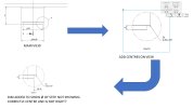
I have a view which shows a step on the part. I've given it a detail view, increased the scale and positioned on the sheet. I then want to dimension the diameters. I thought I'll add a centre line and then dimension to that, then overide the dimension with the figure it should be. Not really knowing if there is a proper way to do this type of thing?
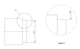
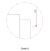
Anyway, the results are shown on the attached image. Clicking inside the view and selecting centre lines gives me a centre line but seemingly not the correct middle? When I try and dimension from the edge to the centre line I get what is shown. I've added what the diameter should be so you can see it's a way off.
Something doesn't seem to be displaying properly? I can bodge it for the purpose of getting the drawing done but anyone have any ideas, or a way of picking up that diameter properly in the detail view?
Cheers
I have a view which shows a step on the part. I've given it a detail view, increased the scale and positioned on the sheet. I then want to dimension the diameters. I thought I'll add a centre line and then dimension to that, then overide the dimension with the figure it should be. Not really knowing if there is a proper way to do this type of thing?
Anyway, the results are shown on the attached image. Clicking inside the view and selecting centre lines gives me a centre line but seemingly not the correct middle? When I try and dimension from the edge to the centre line I get what is shown. I've added what the diameter should be so you can see it's a way off.
Something doesn't seem to be displaying properly? I can bodge it for the purpose of getting the drawing done but anyone have any ideas, or a way of picking up that diameter properly in the detail view?
Cheers