Took a while to track this down,
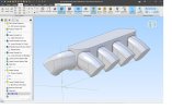
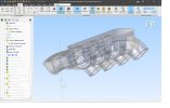
The issue was with the paths for the 2 sweeps early in the design - these led to failed edges (revealed by running check part just ahead of the shell feature). Making the curvature in the paths a little gentler by moving intermediate spline points restored normal service.
Thanks very much for taking the time to do that David.
I think I've I learned something very valuble here. I haven't been using "check part" but found it on the inspect menue. Now I just need to get better at understanding what it's telling me and how to fix the errors

I looked at the docmentation and gather
check part is sort of the 3D object analog to
analyze for examining a sketch. When I select it on the file I posted, I do see the 7 failed edges and 3 failed vertices. I see I can highlight and identify the location of the failed features on the model and save the report. In this case, it displays the same regardless of location in the DE history since the sweeps are the first geometry created, but if they were not, I presume I could just keep moving up the DE history to find offending features.
So two questions:
1. An object can have failed features/errors but still not display as failed in the DE? Is that (apparently) correct?
2. If a part has failed features, it may or may not still allow the end model to successfully generate depending on nature of erros and end model? In this case, the solid seems to generate ok, but even though the inner shell surface
seems to generate, the shell causes the display error.
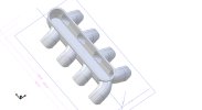
3. The runner fillets on my model were nut fully/correctly formed. It appears they are in your model. Did that happen with the spline changes or can the locations where the fillets merge can be independently changed. Your contrcution lines/fillet merges appear to be in different locations than my original model. How did you do that?
Probably more than you want to know but, I started this version of the model to see if I could make a parametric model that allowed me to easily how the runner cross sectional area increased along the guide curves. At one point I had the splines/guide curve sketches fully defined but I removed the constraints and had been moving the spline points around on the sweep guide curves to achieve design objectives or prevent other feature failures and that indeed is when the transparency problem showed up.
I've made it quite difficult on myself with the shape of the center plenum and all the other design requirements. Meeting all the design objectives/requirements while keeping the modeling functins in balance without failures is barely possible with the physical size and proximity of the various features. I have several other versions of this model. One uses 3D guide curve controlled lofts to generate the runner tubes but I can never keep the lateral surfaces of the runners parallel (which makes machining the result model more pratical) to the Z-axis with that method.
Surprisingly, with all the power and design freedom available in the sweep and loft functions, the only way I seem to be able to meet all of the design objectives is with a simple set of extrusions and cuts from 2D sketches. However, one of the required sketches is very complex and not easily changed, but I think this tends work better because instead of being construction mish-mash of solid shapes stuck together it creates the solid geometry with fewer object and tends to flow and grow more consistently with the shape of the runner tubes. That makes less complex solid geometry for shell and finsihing fillet functions. I say surprisingly because that method seems to be the least sophisticated modeling technique, but I guess less sophisticated also means less geometrically complex in this case. If I get better with using equation driven shapes, I may eventually have a more adaptable model with this method.
-Still learning!
Best,
Kelly


