What's new

Do not recognize this weld symbol

JST

Alibre Super User
And, it seems that GMD will not apply it, so I may have to draw it.

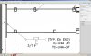
I THINK it is a v-prep weld, with backer, built up to a fillet, welded all around with a certain specification. I do not have that option in GMD. No backer is shown on any of the engineer's stamped drawings.

I'm not even sure it is a totally valid symbol, since the textbook for my welding class of several years ago does not include it. I am not certain about the specification, either.

If it can be translated differently, or even if I have it right, is there a relatively standard way to show this?
 

Attachments

  • weld.jpg
    weld.jpg
    320.9 KB · Views: 21

MikeHenry

Alibre Super User
I've no clue but Googling "AWS welding symbols" turned up what looked like several useful charts. My apologies if you've already tried that.
 
The symbol (sort of) decodes to: (A) far side is a slot or plug weld and near side as a bevel weld. I doubt that whomever created it is familiar with AWS Welding Symbology.
 

JST

Alibre Super User
Lew_Merrick said:
The symbol (sort of) decodes to: (A) far side is a slot or plug weld and near side as a bevel weld. I doubt that whomever created it is familiar with AWS Welding Symbology.

That is also what I suspect, as the far side is not very accessible. The flange on the end DOES have a hole in it, but it is far from being good access to back side. No clue how a plug weld or slot weld would be done there. That's why I punted to a "backer" symbol, which it also resembles

There are a couple other "creative" symbols.

But, it's the PE drawing, and unless someone countermands it, we'll need confirmation from the PE in question. It's a couple hundred feet up on a monopole un-guyed cell tower, the ones that look like (very) faux pine trees. No place to be guessing.
 

HaroldL

Alibre Super User
The way I read it is that it specifies an all around bevel weld with "backing" followed by a fillet. If the backing is to be removed after the weld is done there would be an "R" inside the rectangle. The backing material should be called out in the tail.
 

JST

Alibre Super User
What you see is what is there.

What you suggest is what I came up with also.

I am not entirely familiar with the "stacking" of symbols, and I DO know (or think I do) that there is no way to do that in GMD. Maybe in Revit there is, a lot of folks use Revit for electrical and mechanical work.
 

HaroldL

Alibre Super User
JST,
While GMD does not have the ability to stack the weld symbols you can stack welding symbols manually. (I read somewhere that this is the preferred method.) For the second and subsequent welding symbol just place it without the leader arrow and align it so the leader(s) are aligned with the first leader.
I think the weld joint designation should be on the first welding symbol since it sets up the weld joint. For the backing I used the Plug or Slot weld symbol since in this case it does designate a backing. If the symbol is used by itself then it would be a Plug or Slot weld. GMD is missing some functionality in the welding symbol generator, there is no way of indicating the removal, if required, of the backing unless you place a "R" as a separate text note on top of the weld symbol.
The second or fillet, in this case, would just indicate the fillet weld and size. Both would have he All Around symbol.

Here's my take on it:

And with the removal of the backing:


BTW, if you google TC-U4A or TC-U4A-GF there is a lot of discussion on the AWS and Eng Tips forums.
 

Attachments

  • STACKED WELDING SYMBOLS.png
    STACKED WELDING SYMBOLS.png
    4.7 KB · Views: 440
  • STACKED WELDING SYMBOLS w-R.png
    STACKED WELDING SYMBOLS w-R.png
    7 KB · Views: 438

JST

Alibre Super User
I did more or less what you suggested. We'll see how that flies, all of these shop drawings get reviewed/approved by the engineer. The original "creative" symbol I have not seen anywhere when looking for info on it.

I did google the spec, and found this, which is pretty helpful. Had some more info past my welding text. Never having done commercial welding, I had not run across all the process tails.

https://forums.autodesk.com/autodesk/at ... ailers.pdf
 

HaroldL

Alibre Super User
I saw that link when I searched for the weld designation. It would be interesting to "hear" his presentation, he could probably tell some interesting stories about welding symbol application. It is a good read though, goes way beyond the basic info that is presented in the technical college.

JST said:
. . . The original "creative" symbol I have not seen anywhere when looking for info on it.. . .

If you search for "stacked weld symbols" or "stacked welding reference lines" you should get a few hits and if you haven't already, take a look on pg 36 there is an example of a stacked weld symbol and pg 69 illustrates the backing weld.
 

JST

Alibre Super User
Looking up stacked symbols, I found NO examples of stacking as the engineer did it. Not even in the images.

The page 36 case may be an "option", as the stacked symbol is dashed, and an apparent alternate form of weld is also shown dashed at left. It is not clear that it is actually "stacked", i.e. both to be used at once. I just do not know, and admit it.

What I did was to use the multiple arrow method, and specifically called it out as a question when I sent in the drawings. It will presumably get sorted when reviewed.

The stacking is only one issue. The rectangle symbol appears non-applicable or potentially confusing in the situation as well (backing bar? Plug/slot?). We'll see.
 

HaroldL

Alibre Super User
Yeah, that's probably not a good example for a stacked weld symbol. Here's a link to a pretty descriptive text on the use of welding symbols for use on structural welds (it's actually AWS D1.1:2000). It has several examples of stacked weld symbols, some in dashed line font, along with an illustration of the weld joint. The dashed weld symbol corresponded to an extra component of the weld joint that also was shown in a dashed line font. My read on it is that "if the component is present then apply this weld".

As for the question of the backing weld, you have to read the symbols in context of their usage. I came across this AWS blog that may shed some light on it.

It would be interesting to see what the PE has to say about it.
 
HaroldL said:
It would be interesting to see what the PE has to say about it.
Assuming this had been "aimed" at me, I maintained currency to AWS D1.1 through the 1985 update. Since then, my primary non-garden-variety welding has been aimed at aluminum and magnesium vacuum systems. Those systems, being either medical or orbital in nature, fall under a completely different specification set. I have not followed AWS D1.1 closely since 1985, I admit it.
 

HaroldL

Alibre Super User
Sorry Lew, No, I was referring to the engineer that JST is submitting his drawings to,
JST said:
. . . all of these shop drawings get reviewed/approved by the engineer. . . .
assuming of course that, since he is signing off the drawings, he is a PE.
 

JST

Alibre Super User
He is, stamp on every page.

I looked through a more recent AWS document linked here, and didn't find stacked symbols, but I obviously didn't go through all 499 pages.

We'll see.
 
Hello,
Please forgive my bad english..

AWS D1.1 is the code for steel structures. you will find something here but there are best sources from AWS.
Regarding symbols the best source to understand the symbols is "AWS A2.4" you can get a copy using google (http://design.medeek.com/resources/DOCUMENTS/AWS_A2.4-2007.pdf). One good example is shown on figure 27.
Another good source of reading concepts is AWS A3 (standard welding terms and definitions)

I hope i could help you clarify some concepts
 

HaroldL

Alibre Super User
Thanks nichterlein.
(FYI, your link is acting a little weird, I had to backspace in the address bar to DOCUMENTS/ before I could get it to work.)

Actually, a reference that answers the question the best is paragraph 5.5 Combination Weld Symbols. 5.7 covers using multiple reference lines to clarify order of operations. 5.5 also indicates order of operations if the welds are applied starting with the reference line and working outward.
 
Top