What's new

Drawing with visible dimensions.

Jim T.

Member
Thanks to everyone for all your help, this forum is awesome. Had to catch up on my phone, at a DOT medical exam for my CDL renewal at the moment!
 

Max

Administrator
Staff member
So any annotations that I make in the 2D drawing will update the 3D model, even if the dimensions in the 2D drawing aren't the same as the ones that I use to create the 3D model?

So there is confusion in the answers to this.

There are 2 classes of dimensions that can be in a 2D drawing.
1. Design Dimensions
- These are dimensions that you created during 3D part creation. Sketch dimensions. Extrusion lengths. Revolve angles. Things like that.
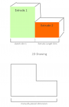
- You can optionally project these dimensions during view creation in a 2D drawing via a checkbox. However you will often find, unless your part is trivial, that these dimensions do not correlate with what you want in a drawing. See image example below.

2. Regular Dimensions
- These are dimensions you place manually in a 2D drawing. These are a "reflection" of the part's geometry, whatever it happens to be. You place these because you need to call out information in a specific way.

In a drawing, you can edit Design Dimensions (if projected) by double clicking on them in a drawing. When you edit a design dimension, the 2D drawing will be recalculated with the new dimension. You will see a physical change in the 2D drawing happen in real time. If you were to save the drawing, you would also be prompted to save the part (since it has now changed). You are able to edit design dimensions because they came from the part model - they have a 1 to 1 meaning with a very specific thing in the model - the length of a particular line, for example.

In a drawing, you cannot edit regular dimensions. They are a "reflection" of the geometry. They tell you what it is, but are not the recipe to make it. While these dimensions often have a one to one meaning (to your eyes), they very often do not have a one to one meaning in the context of a 3D model's parametric recipe.

Let's take a simple example:

1651261253800.png

You might want to manually place the dimension on the bottom and then be able to edit it. However, how should we change the underlying model? Do we change the sketched line dimension? Or do we change the extrusion length dimension? This is a trivial example, but is meaningful in that it illustrates that you often do not design parts, especially more complex parts, in the same way you end up dimensioning them in a drawing. If your part is a plate with holes in it, then sure design dimensions are probably useful. They are probably generally applicable more to 2.5 axis machined parts, but when you start to get into 3 axis / 3D printing etc. where you're adding things and removing things in the model to end up with what you want, design dimensions are often almost totally irrelevant to the final drawing product because they often have zero correlation with anything meaningful in the drawing.
 

Jim T.

Member
This is exactly the way ProE/Creo, SolidWorks, and Catia work, but I’ve always used what we called “driving dimensions” in the drawings. In your example above, instead of adding an extrusion to the model, I would have edited the original feature. I know it’s a simple example and there are definitely cases where it is advantageous to add the extrusion, but in 27 years of 3D modeling on various systems for Honda and Delta Faucet, I’ve never used what we called “driven or reference dimensions”. Not to say I’ve not placed dimensions manually in drawings, but these always came in the drawings inside parentheses automatically, or I added the parentheses manually, thereby identifying them as reference dimensions. So is it common practice in the Alibre Design platform to create dimensions on the drawings rather than use the ones created while modeling the parts?
Thanks again for all the help you folks have provided. Alibre definitely stands alone in how it works as opposed to the other systems I’ve used, and because of this, has proven to be more difficult for me to learn and understand.

Thanks again everyone!
Jim
 

Ralf

Alibre Super User
Hi Jim,

Only through dimensioning is the geometry of a component or group of components precisely defined on technical drawings.
However, dimensioning can be done in different ways, in ALL 2D and 3D CAD applications.

In practice, there are essentially three different dimension entry systems in use.
Thus, the dimension entry can be either:

- Function-related
- Production-related
- Inspection-related

Function-related dimensioning systems

Function-related dimensioning is used in technical drawings whenever the exact function of a component or assembly is to be shown exactly and clearly in the drawing. In this case, the dimensions are selected and entered in such a way that all tolerance ranges that are decisive for the technical function of the component or component group are exactly defined, comprehensibly represented and completely present. Neither the production nor the testing of the component needs to be taken into consideration. Anyone who already has practical experience with the creation of technical drawings will certainly be well acquainted with this type of dimensional entry.

Manufacturing-related dimensioning systems

With this type of dimension, the focus is on the manufacture of the component, especially with regard to all the manufacturing processes that will be used. Production-related dimensioning systems include functional dimensioning because after all, the functional capability of the component or component group must be guaranteed after production. Complicated dimensioning, in which the individual dimensions must first be converted into other dimensional units, must be avoided at all costs. After all, they serve the manufacturer as a basis for production and must not make his work even more difficult.

Inspection-related dimension entry systems

All dimensions, tolerances, and tolerance chains required for exact component testing must be entered in the technical drawing. Care must be taken to ensure that all information is unambiguous and that no conversion of dimensions or tolerances is necessary at a later date. The type of dimensional entry must be made in accordance with the prescribed test system. The "test drawing" created in this way is used for quality assurance purposes and, in addition to the various measuring instruments, represents the most important working tool for the tester.

+++

All 3 three different dimension entry systems can be created with Alibre Design PRO and Expert without any problems.

+++

As already noted above:
The direct transfer of dimensions/your dimensions from the 3D Part to the 2D Drawing can be done via:
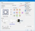
Design-Dimensions.jpg

+++

Each CAD application is different from others and it is your job as a user to understand them, (and the differences between them)
even in NX, CATIA, SWX, Inventor, SE, Creo Parametric,...

I'm sorry to say this, but it can't be done hastily as you are trying to do, at the moment.
 
Last edited:

HaroldL

Alibre Super User
This is exactly the way ProE/Creo, SolidWorks, and Catia work, but I’ve always used what we called “driving dimensions” in the drawings. In your example above, instead of adding an extrusion to the model, I would have edited the original feature. I know it’s a simple example and there are definitely cases where it is advantageous to add the extrusion, but in 27 years of 3D modeling on various systems for Honda and Delta Faucet, I’ve never used what we called “driven or reference dimensions”.
It looks like your experience is unique. Was the use of "driving dimnensions" a company standard or policy? All my training and use of 3D CAD is limited to SolidWorks but the standard that was set at my work was to not use model dimensions. It was covered a little in training but not promoted as "the way" to dimension drawings. We had master models set up and to derive other sizes of a model we would modify the model and update the drawings. Changes were not pushed from the drawing to the model. Even through the use of Tacton configurator all the drawings never had a model dimension on them.
 

Jim T.

Member
Good morning Ralf, RandyL, HaroldL, and anyone else who has contributed to this thread.
Thanks for very intuitive replies. I really appreciate the time all of you spent on them in order to try to help me! That said, I have a few comments.

First, I believe the standard at both Honda (Catia) and Delta (ProE/Creo) was to use model dimensions. There were a few outlier engineers who adhered to the policy more loosely than the masses and no engineer wanted to be the next to update their horrible drawings because nothing was connected (parametric).
The design of a product or tool is already in the mind of the designer before he ever sits down at the computer. Because of this, the model creation and dimensioning schemes are already there as well. The CAD was never used as a tool to “discover” the design as you go along. It was only a tool to get what’s in your brain onto the black and white. So the modeling was done with the final product (the drawing) in mind. With a key stroke, all design dimensions are shown on the drawing, and only rearrangement of the dimensions was needed (there are CAD tools for that as well) in order to provide a “clean” drawing. Tolerancing was done to each dimension by number of decimal places, bilateral, unilateral, or applied GDT. The tolerance applied to each dimension controlled the functionality of the design as well as the means by which the tool room, or production machinist finished product. Surface finish callouts were applied in the drawing mode. Inspection dimensions were applied on the drawings and an inspection instruction sheet accompanied the drawings for the QA inspector whether product or tooling.

As for trying to hastily learn AD, I see it only as a tool for bringing what is in my mind to paper. I’m not trying to learn engineering, design, or drawing skills as these have already been developed over my career. I only seek to learn and understand this new tool called AD to accomplish these things.

Please don’t read this as arrogant or the like as you have all been very forthcoming in helping me and I greatly appreciate it. To my surprise, even my son, a recent Purdue grad (following in my footsteps) agreed that model dimensions are not used on drawings. He said that we must’ve been conditioned at Delta to use model dimensions.

So there it is, I guess I’m old and out of touch!!

But seriously, I think that now that I’m engineering product with a plus/minus quarter-inch tolerance as opposed to the half-thou (.0005) tolerances that I’m used to, I’ll still attempt to use the model dimensions.
My problem was with getting them to “show” on the drawing, and then moving them around to clean up the drawing, which I believe one of you revealed above.
Again I thank all you for your help, and I look forward to more intelligent and interesting conversations on here in the future!!
Have a great rest of the weekend everyone,
Jim
 

Ralf

Alibre Super User
Hi Jim T.,

Yes, it is your decision what form/type/... of dimensions you use in your 2D Drawing(s).

+++

First, I believe the standard at both Honda (Catia) and Delta (ProE/Creo) was to use model dimensions.
So you only believe?
You haven't worked with CATIA at Honda and with ProE/CreoCreo at Delta yourself?

+++

There were a few outlier engineers who adhered to the policy more loosely than the masses and no engineer wanted to be the next to update their horrible drawings because nothing was connected (parametric).
This is incorrect because "Parametric" is also the manual dimensioning of edges, vertexes, etc...
updated in the 2D Drawing(s) after changes in the 3D model. (Alibre - > Reproject Views)

+++

If you want, here is a video with Max Freemann the CEO of Alibre
Unfortunately, you have ignored his post #23
 

Jim T.

Member
Uhh, yeah, I worked at and used ProE/Creo for 17 years at Delta, I'm just not sure if it was mandated that we use model dimensions or if we (the engineers) decided to do it on our own because it made life easier down the road, but we absolutely used model dimensions in both product and tooling drawings.

I watched the video above, very interesting. I like the goals of the company in making CAD affordable for the hobbyist, etc., and the active role that the CEO takes in knowing who his customers are and what they need in order to be productive.

I still have the problem of dimensions that I created in an assembly that I cannot show in the drawing. As HaroldL says in #18 above, it doesn't look like the option is available.

Thanks,

Jim
 

DavidJ

Administrator
Staff member
Dimensions in an assembly? Do you mean constraints, or did you use some assembly features?
 
Last edited:

Jim T.

Member
Not assembly features because it doesn't look like there's an option for an extrude feature for adding material in the assembly module.
I had originally assembled the first in a line of tanks to the default datum planes of both the first tank and the default datum planes of the assembly module. This basically locked all three default datum planes of the first tank to the same default datum planes that come in when you start the assembly module. Next, I offset a datum plane in the assembly module from the default datum plane of the assembly module to what would represent ground level. This created a datum plane that is above the row of tanks and represents the ground level and is constrained to the assembly datum. Next, I create a drawing and inserted the entire assembly (tanks, piping, pumps, filters, etc.) into the drawing with a front (landscape) view. My intent was to be able to show the assembly dimension (the distance of the offset of the ground level datum plane) of how far above the top of the tank the ground level was, thus a dimension showing the buried depth of the tank.
I cannot get the offset dimension to show and I have nothing to dimension to.
So I liked the suggestion of creating a chunk of earth behind the tanks to represent the ground level in the drawing, but I'd rather just show the dimension representing the offset of the datum plane that I offset above the tanks that represents the ground level.

Thanks,

Jim
 

HaroldL

Alibre Super User
So I liked the suggestion of creating a chunk of earth behind the tanks to represent the ground level in the drawing, but I'd rather just show the dimension representing the offset of the datum plane that I offset above the tanks that represents the ground level.

Since displaying design dimensions in an assembly drawing is not an option it may be the only option you have is to use the Sketch in View method I illustrated in post #21.
Even in a part drawing the dimension for an offset plane will not display as a design dimension and I don't know that there is a way to make it do so. Only if you created some feature on the plane and had a dimension to the feature then that dimension may display on the part drawing.
 

Jim T.

Member
Thanks HaroldL

There is a post above, OTE_TheMissile, that also suggests creating a tiny sphere so that a dimension can be created and then shown in the assembly, kind of what you are suggesting here. I'm looking into DavidJ's #20 idea of just creating earth behind the tanks at the proper height in order to be able to show a dimension. Not sure what the Sketch In View is that you suggested earlier either, just need to investigate some of this stuff further, I'm sure I'm not the first to run into this, and there's probably a way to do it!!
 

HaroldL

Alibre Super User
Not sure what the Sketch In View is that you suggested earlier either,
Did you watch the video that I linked to the post? You may need to turn up the volume on your computer since the audio is a bit low. (sorry about that. :oops: )
 

Jim T.

Member
Not yet HaroldL, probably get to that this evening, meant to do it over the weekend, but was in a CMV most of time hauling crushed stone...
 
Top