What's new

Editing print_processes.xml

bigseb

Alibre Super User
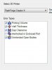
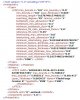
So I am editing the print-processes.xml file. More for jollies and to see what all I can do with it. Got rid of all the extra 'stuff' and adjusted the parameters to suit the abilities of my printer and slicer (FlashForge Creator X and Makerware 2.4 respectively). Hit a few snags so I'm hoping someone can fill in the gaps:

- what programming language is this?
- how do I change units from inches to mm? Having to convert at the moment...
- it no longer shows the overhang angle check in GD. I don't know why.
- What is the GUID referencing to? Do I need it?

Thanks
 

Attachments

  • print_processes.zip
    676 bytes · Views: 3
  • Capture.JPG
    Capture.JPG
    89 KB · Views: 13

ajayre

Alibre Super User
It isn't a programming language. It's a text-file format called XML. Designed to be easily human-readable and editable.

https://en.wikipedia.org/wiki/XML

GUID = Globally Unique IDentifier. My guess is that you should probably come up with your own that isn't used elsewhere in the file. That is likely the only requirement, but without seeing the GD source code we cannot know for sure. Used to tell different printer definitions apart. Might be stored in a preferences file somewhere to indicate the currently selected printer, or might be stored in AD_PRT files to indicate which printer is used for that part.

Note that GUIDs are usually of the format you see later on in your example for the FFCX GUID. I've never seen one that looks like "FDM". I'm surprised the software accepts "FDM" as valid.

https://www.guidgenerator.com/online-gu ... rator.aspx
 

BobSchaefer

Senior Member
So, taking a best guess as to what's what in this file, based purely on what you show of the file and what is typically expected in a configuration file, here's my thoughts on things:

First, most likely you can't change the units, they're hard-coded in the application somewhere, although I find it interesting that GD would default the printer specs to imperial units when it uses metric for the parts internally.
Second, as ajayre points out, XML is not a language, its simply a markup, like HTML, in fact HTML is a specialized version of XML.
Next on the GUID front, its an identifier, traditionally, it looks like what's in the FFCX GUID="..." section, a big long list of letters and numbers (actually a 128 bit hexadecimal value in this case). However, nothing says it has to be that, its just an identifier.
Finally, no idea on why something would stop showing up, other than to say it probably got confused by something else that is actually causing the problem, maybe the GUID you entered for the type.

Oh, and just to help you out, it looks like the TypeGUID field in the Printer node should match the GUID entry from the Type node above it, just in case you hadn't figured that out yet.
 

bigseb

Alibre Super User
Thanks guys.

ajayre said:
I've never seen one that looks like "FDM".

It was initially a long code but I changed it to FDM. Should actually be FFF...

BobSchaefer said:
Oh, and just to help you out, it looks like the TypeGUID field in the Printer node should match the GUID entry from the Type node above it, just in case you hadn't figured that out yet.

Starting to sink in... :)

One thing I still don't get is why the overhang angle (45 deg) isn't showing in the GD window despite being in the xml file...
 

bigseb

Alibre Super User
bigseb said:
One thing I still don't get is why the overhang angle (45 deg) isn't showing in the GD window despite being in the xml file...
To follow up on this see the following two images:


In the first one where 'none' printer is selected it shows the overhang check box but in the second image where 'FFCX' printer is selected this option is missing. Why is that? The code above clearly shows the option. Did I deactivate it somehow? Really stuck on this one...
 

Attachments

  • 01.JPG
    01.JPG
    22.1 KB · Views: 204
  • 02.JPG
    02.JPG
    21.2 KB · Views: 204

BobSchaefer

Senior Member
First, remember I'm going off guesses based purely on what I'm seeing here, I haven't played with anything in the application, yet. So my first question would be, are there other entries where the checkbox is showing up that would show what the entries should look like? If not, how did you decide on the names? Maybe there's another option that is needed in order for it to show that you've missed, things like that.

Next, is this part of the standard GD install? Where can I find these files on my system? (Where are they on yours, then I can find them on mine, maybe) I have the full version, but a couple of revisions old, as I got tired of paying for maintenance and getting less and less every year.
 

ajayre

Alibre Super User
BobSchaefer said:
Next, is this part of the standard GD install? Where can I find these files on my system? (Where are they on yours, then I can find them on mine, maybe) I have the full version, but a couple of revisions old, as I got tired of paying for maintenance and getting less and less every year.

If you don't have the "printability" options in the ribbon then you won't have the file in your installation folder as your version is too old.
 

bigseb

Alibre Super User
UPDATE:

Finally got it working. Here is there latest. I think it simply drop certain options because I set the tolerance to zero but that's a guess as I am not an xml expert.

The Printability function is not that bad actually. It confirms that wall thicknesses, gaps, overhangs, etc are within acceptable preset parameters; a kind of a confirmation if you will. Very handy for intricate models. And it will let you output a model in the correct orientation.
 

Attachments

  • print_processes.zip
    728 bytes · Views: 6
Top