What's new

First post, self-teaching, saving loses changes

KB58

Member
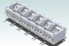
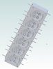
I'm teaching myself Alibre by watching a YouTube expert create a cylinder head.

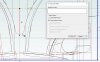
Other than having to stop the video a million times to do what he's doing, it's very helpful. The problem is that part way along, I try to save what I've got by left-clicking on the "disc" symbol. It does save, but all changes other than the basic extrusion vanish. That is, I get up to around 4:20 in his video, save it, and all the references, constraints, and dimensions disappear, except for the basic rectangular shape. Through trial and error, I found that the same thing happened (once?) when deactivating 2D sketching. I realize that there's also a chance that everything is still there, possibly disabled or moved to another layer, but I can't figure out why saving would affect what's currently displayed.

I don't see this listed as a common problem, so I'm fairly confident that I'm being boneheaded, somehow. Happy to have how, pointed out to me!

Thanks
 
Last edited:

HaroldL

Alibre Super User
When you save the file Alibre will exit out of sketch to do the save. The same as if you had exited sketch before saving.

BTW, Have you gone thru the Alibre training manual videos? They may give more insight on the functions of Alibre Atom or at least explain more.
 

KB58

Member
Oh there's tons I need to learn about. I think I know what's happening, or at least, better understand what's acting unexpected. When I hit save or Exit Sketch, it's flipping the object completely around so that I'm facing the other end of it. My work is still there, but only becomes visible when zooming out to see the entire object. I shall scurry off to go through the training manual videos. I'm using Design and did find the training link, so thank you.

The last CAD I used was, don't laugh, Google Sketchup, and designed an entire tube frame car with it (midlana.com), and even at this stage, it's clear that this is superior. Thanks for the quick response!
 
Last edited:

HaroldL

Alibre Super User
If you're using Design then the link I gave may not give a complete training since it's for Atom3D. This is the landing page for training on both, so pick your choice.

If the part is flipping around when you exit sketch mode that is Reorient on extrude, you can turn that off on System Options. I find it easier to work in AD with it off.
Reorient.png
 

H-L-Smith

Senior Member
@KB58

Hi Kurt,

It looks like you're on your way with some answers. You'll find the user community here very helpful and quite expert. Alibre is more complex than Sketchup, but many times more powerful. It takes a little while to get comfortable with it.

I understand your interest in the cylinder head tutorial, but if you find it too frustrating, do some smaller projects first to get your basic interface skills and product knowledge up to speed.

Cheers,

Lonnie in Carlsbad
 

KB58

Member
I checked Reorient on extrude and was surprised to see that it's disabled by default, so something else is going on to cause the project to change on saving it. In any case, I'll press on with the training.
 

DavidJ

Administrator
Staff member
Use the 're-set view' button on the sketch ribbon to flip the sketch around if it opens 'facing the wrong way'.
 

KB58

Member
Update: Okay, I went through all the video training, then returned back to following the YouTube videos of creating the above cylinder head. I've successfully made it almost all the way through, but got stuck on what seems like a very simple thing.

If you go to Part 3 of the cylinder head video, below, and jump to 39:50. Right at 39:58, he does a Project to Sketch of a U-shaped trough, to bring a reference to his working plane. It works as expected in his video, but I'm unable to select the U-shaped bit, or any other edge for that matter. Note that this takes place on an internal plane through the head, and in my situation, Project to Sketch only seems to be "seeing" the front side of the entire assembly, not the internal plane that I'm working on. This is especially confusing since I had no issue successfully added the vertical line above as he does, which does get created on the internal plane as expected.

I feel like I'm overlooking something really simple, but can't figure out how I got this far, only to get hung up on this bit. Thanks in advance!


Below is a screenshot of where I'm unable to select the U-shape to project it into my sketch.
 

Attachments

  • cylinder head1.jpg
    cylinder head1.jpg
    112.1 KB · Views: 8
Last edited:

HaroldL

Alibre Super User
Go to Tools>Selection Filters>Solid and select Edges. That should let you select the internal edge.

If you set up some Hotkeys you can toggle your selection filters on the fly so you don't need to go to the menu to change them.
 

KB58

Member
Ah, hiding behind the Alt key, a whole 'nother world that I didn't know about! Thank you.

Okay, and hopefully the last thing, which is what actually got me stuck. At 42.15 in the same video above, he does a sweep cut of the path just created. When I do it, it fails, with the status error "SWP_ERROR_MULTIPLE_PATHS: Path Objects result in more than one continuous path for sweep." I've deleted and redrawn the path several times, trying different things to discover what I'm doing wrong, but can't figure it out. I've fairly exactly copied his model, so everything is in the same place, but for some reason mine doesn't like the path. Any ideas? I can take a screen shot, but it looks just like his, a straight segment and two arcs.

Thanks again!
 

HaroldL

Alibre Super User
Double check your path sketch to make sure there is not overlapping sketch figures. Use the Sketch Analyze tool, under the Sketch menu, to check it. The tool will tell you if there are any errors in the sketch. If any show in the Results box select it and see what highlights in the sketch.

Another thing to check is the arc that was projected from the curved edge. Make sure that it is Reference geometry if it is not that could cause the problem too. RMB click on the sketch figure and check if the option to convert to reference geometry is active. If it is then select it to convert the projected arc to reference geometry. That may solve the multiple path problem.

convert to ref.png

One more thing, he is using a 3-point arc to make the arcs then applying a tangent constraint between it and the vertical line and another tangent constraint between the first and second arc. Right next to the 3-point arc tool is the TANGENT ARC tool, use that instead and you won't need to apply tangent constraints later. I am surprised that he missed that since the icon is so large. When using the tangent arc tool you don't select the end point, select the sketch figure you want the arc tangent to.
 
Last edited:

KB58

Member
Thank you to everyone who helped me out. I completed the model, and it helped enormously to follow the videos during its creation (I'm a "show me" guy). Unlike his model, I added filets and spark plug holes, hah.

I realize that I have a long way to go - Alibre is a like wandering through a big building, just when I think I have it mapped out, I find another hallway, but this has big a big boost in my confidence. Thanks again!
 

Attachments

  • cylinder head2.jpg
    cylinder head2.jpg
    83.5 KB · Views: 18
  • cylinder head3.jpg
    cylinder head3.jpg
    50.7 KB · Views: 16
Last edited:

HaroldL

Alibre Super User
There is a lot to digest in his videos. If you want something a bit smaller to practice on I put some links here in the
Tutorials and Tips from the Community section. They don't have any narration describing the process but are good to practice on for new users, and maybe some old ones too.
 
Top