What's new

Flange Creation Issue/Question

bRIBEGuy

Member
Hi Everyone,
I'm using Alibre Design Expert V23, and trying to create angled bends at the edges of a sheet metal part. If I use the "Flange" tool and roll the flange to 90 degrees (inside alignment) it works great, and keeps the edge-to-edge dimension of the original part. The issue is that I need to have the the flange at a 30-45 degree angle, and when I do that, the flange "creeps" outward, increasing the edge-to-edge dimension of the original part. Is there a way I can create a bend like this while preserving the edge-to-edge dimension of the original part?
Any assistance is appreciated...
 

HaroldL

Alibre Super User
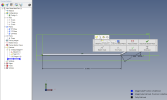
You could use the Contour Flange tool. Just sketch a single line profile of the part with the flange/bends as needed.
sketchedbaseflangesketch.png

Can you upload your part or a sketch of what you are attempting to make?

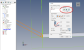
You can also check the Flange Alignment setting and see which one fits your needs for the part:

flange alignment.png
 
Last edited:

bRIBEGuy

Member
The alignment tab seems to change the location of the bend, but doesn't impact the leg. I was hoping that the alignment options would control both as they do in a 90 degree scenario.

I've attached a quick sketch trying to show what I'm working with. 4/8 sides require a bend to bring material height up to 0.25". I was hoping to use a 30 degree bend for this, as a 90 is likely not possible to actually produce. The part needs to be 7" across. Using the 90 degree bend (inside alignment) it works fine. Less than 90 degrees and it does not (30 degrees yields a 7.433" width). My attached sketch shows both flange setups. :(
 

Attachments

  • New Sheet Metal Part (ForumTest).AD_SMP
    454.5 KB · Views: 3

HaroldL

Alibre Super User
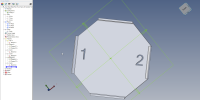
If you need the blank to remain at 7" across the other flats then I see you have two options; 1) is to create a notch for the flange to be created from or 2) is to trim off the edge you want the flange on. Either way Alibre does not have a "Offset" option for the flange, only the Alignment settings. To hold a dimension like you want from flange to flange you need to adjust the starting edge and in this case it may be the notch or trim.

Here is your part with the two options shown on flange marked 1 and 2.

I was hoping to use a 30 degree bend for this, as a 90 is likely not possible to actually produce.
Yeah, forming a .25" flange on10 Ga material is going to be tough. Unless you have special punch and dies made you may need to create the flanges longer then machine them to the required length. At my old employ we had similar forming issues and trim after form was a practice that was adopted for those parts.


And, Welcome to the forum.

Offset Bends.png
 

Attachments

  • New Sheet Metal Part (ForumTest) with Notched Trim Cuts.AD_SMP
    660.5 KB · Views: 2
Last edited:
Top