What's new

gear constraints

I've been back and forth with support about getting gear constraints to work. My motion study whirllygig is ready to go except for the fact that I can't get one gear to drive another. To one of the women in support I sent a package file of the entire mechanism. She said she got it to work, sending back a screen shot of the tree with the gear constraint in green. She sent be back her package file but the gear constraint wasn't in hers. I tried installing the gear constraint on her file but when I try to populate the parameters of the box regarding the two gears on the "mechanical side of the constraints the "apply" is greyed out. I've tried working with two different keyboards because I was having issues with one that I knew of (several letters I have to hammer to get them to put out data) @ " and several others, I ALWAYS have to HAMMER the @ to keep from putting out a "2". I got my gears from McMaster-Carr. They have a massive selection of 3D modeled hardwar in multiple different formats IGES, STEP etc. I slice it up as fars as the thickness, cut a little slot so I can drive the the shaft with the gear thru the angle constraint.

I do all that for the two different gears I think i'll need, Apparently i've got some ignorance about gears because though i make sure both gears have the same pressure angle and proper diameter/radius for the ratio I want, the tooth profiles of the drawing don't match. Frankly it seems to me that untill i get the teeth on both gears to both display with the same profile, regardless of the diameter I'm doomed!!

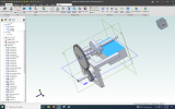
I'm attaching a package files of what I've got going at the moment!!!

If you can get the gears to drive each other I'll be eternally grateful!
 
I don't know if you got both files. One was to be a package file that i'm working with right now and the other was to be a full page screen shot showing the tree for you perusal!!!! What ever you can do will be a big help. Right now I'm frozen to the ground in Arizona!!!!!

I'm shuttling files between two machines with a thumb drive. One is my linux Mint laptop, the other Windows 10 which I loathe I've lived in a Microsoft free world for 15 years!! I only let the windows machine with the Alibre on the internet for the seconds that it takes to transact whatever business is being conducted. Believe me, in my little world you guys are big business!!!!
 
Last edited:

HaroldL

Alibre Super User
Here's a short video on applying the gear constraint. And a package file with the constraint applied for an example.


Attachments

  • completely new assembly partial155_GearConstrained.AD_PKG
    2.5 MB · Views: 0

albie0803

Alibre Super User
both gears have the same pressure angle and proper diameter/radius for the ratio I want, the tooth profiles of the drawing don't match
It seems you have a 32T 16DP gear and a 48t 12DP. The gears need to be the same DP and PA.

I would suggest 32T and 48T 12DP gears which have a center distance of 3.334"

On the McMaster-Carr site DP is shown as gear pitch and they only have common gear sizes

How important is your center distance? To calculate the center distance add Teeth / DP of both gears and divide by 2.

Here is an adjusted model with 32t and 48t 12DP gears with a centre distance of 3.333".
Toothshape is not 100% accurate but close enough.
 

Attachments

  • new gear centre assembly.AD_PKG
    695.1 KB · Views: 5
Last edited:
Thanks y'all for your effort thus far! I got most of the gear constraint issues sorted to this point!!! I'm needing help with some troubling issues of a different nature.

1 when I'm construcitng Alibre just slobbers constraint symbols on. Seems often that i then have to wrestle with Alibre just to clear them off!!
2 the icons at the very top of the page on the left side indicating the relative orientation of the planes are SO SMALL that i just end up stabbing the next till I get the one i want
3 Alibre puts the little mobile tool box right on the place I'm working so I have to move it to continue!!
4 When establishing the dimensions of a piece i just layed down It grabs the wrong feature about 80% of the time! I then have start over picking the feature i want to know about rather the one it grabbed for me! When I'm trying establish the distance between two items it wants to tell me the angles they are
meeting at. That kind of thing!
5 Is there a way to throw a rope around a group of the constraint icons and disappear them?

6 How do I get alibre to orient to one plane or the other with out having wait on what I don't really know at the moment. I work a lot in XY but then I often
i'll need to work from a birds eye view. Boom how do make it switch to that

Thanks David/conservativtroll
 

Max

Administrator
Staff member
1 when I'm construcitng Alibre just slobbers constraint symbols on. Seems often that i then have to wrestle with Alibre just to clear them off!!
2 the icons at the very top of the page on the left side indicating the relative orientation of the planes are SO SMALL that i just end up stabbing the next till I get the one i want
3 Alibre puts the little mobile tool box right on the place I'm working so I have to move it to continue!!
4 When establishing the dimensions of a piece i just layed down It grabs the wrong feature about 80% of the time! I then have start over picking the feature i want to know about rather the one it grabbed for me! When I'm trying establish the distance between two items it wants to tell me the angles they are
meeting at. That kind of thing!
5 Is there a way to throw a rope around a group of the constraint icons and disappear them?
Can you be a bit more specific here? Are you sketching? Making an assembly? In a 2D drawing?
 

DavidJ

Administrator
Staff member
David - try to ask one question at a time, and make it clear.

You may need to turn off inferred constraints - or at least some of them, if you are getting 'too many' constraint symbols on your sketches.

Orientation icons - the first 6 orientation are also mapped by default against Ctrl+D1 thru Ctrl+D6 where Dx represents a number key on top row of main keypad. Maybe add stickers above those keys to remind you.

If you find the in-place editing menu annoying (it can pop up in awkward places), you can disable it. System Options -> All Workspaces -> Sketching : uncheck the box.

Your item 4 - are you trying to set a dimension (dimension tool), or check it (measure tool) ?

If an angle is reported rather than a distance, that shows that the items selected are not parallel (i.e. there isn't a uniform distance to report).
 
Last edited:

HaroldL

Alibre Super User
You can also toggle the display of all constraint symbols from the View menu:

Menu Display.png

or the Sketch ribbon:
Ribbon Display.png

and as shown on the View menu the hotkey Ctrl+Shift+C.
 
Top