kev h
Senior Member
Hi
Have fudged around with a couple basic mould tools in AD but now have a part to do with an uneven split line , so was wondering if anyone would be kind enough to give me any hints or tips on the general procedure in AD.
(It is a low quatity P20 inserted tool so nothing flash in Nylon 6)
This is how i have gone about it so far...
1 Modeled up the part from sample.
2 Scaled the part to add shrinkage 1.02 for 2%.
3 Inserted scaled part into an assembly then added a new part and sketched split line from modeled part and then extruded lower cavity block and saved the new part as lower insert.
4 Then inserted another new part and projected split line view from lower insert to then create upper cavity block and again saved new part as upper insert.
5 Next to edit inserts separately and perform Boolean subtracts using scaled part to produce cavs.
6 Then create some core inserts but not quite sure yet how i'm goin to do that.
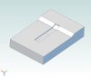
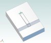
Have attached scaled part and a pic of split line but am redoing it with scaled part now :roll:
Any help/advice would be greatly appreciated especially on how to not tie myself up in knots with assembly constraints and such like.
Cheers Kev 8)
Have fudged around
with a couple basic mould tools in AD but now have a part to do with an uneven split line , so was wondering if anyone would be kind enough to give me any hints or tips on the general procedure in AD.(It is a low quatity P20 inserted tool so nothing flash in Nylon 6)
This is how i have gone about it so far...
1 Modeled up the part from sample.
2 Scaled the part to add shrinkage 1.02 for 2%.
3 Inserted scaled part into an assembly then added a new part and sketched split line from modeled part and then extruded lower cavity block and saved the new part as lower insert.
4 Then inserted another new part and projected split line view from lower insert to then create upper cavity block and again saved new part as upper insert.
5 Next to edit inserts separately and perform Boolean subtracts using scaled part to produce cavs.
6 Then create some core inserts but not quite sure yet how i'm goin to do that.
Have attached scaled part and a pic of split line but am redoing it with scaled part now :roll:
Any help/advice would be greatly appreciated especially on how to not tie myself up in knots with assembly constraints and such like.
Cheers Kev 8)