What's new

Geomagic Design vs The World

bigseb

Alibre Super User
I have been a bit absent from the forums lately and I thought I'd share some recent experiences with the Geomagic Design community. In February this year I was offered a position with a company that designs and manufactures seating, lavatories, galleys and interiors for passenger aircraft, seating and interiors for helicopters and parts for McLaren. This was was a fantastic opportunity so I jumped at it and decided to put my own business on hold for a while. My duties at this new company include product design, mould/jig design and programming for their 3 and 5 axis milling machines.

Naturally all product and part design is done using Catia V5 while all design for in-house manufacturing i.e. mould/jig design and CNC programming is done using Creo Parametric. Its this that I want to address in this post as I have been using Geomagic Design (previously Alibre Design) since 2010 at my own business and have used Solidworks, AutoCAD and Rhino at my previous employment and have had to work with SolidEdge occasionally too. Now though I am being exposed to the big daddies of the CAD world and would like to share how I think they compare to Geomagic Design.

Lets start with Catia. I received two weeks intensive Catia training starting on day one. Let me say right from the start that this is amazingly powerful software. Nothing comes close to Catia. Nothing.This is truly the all-singing all-dancing package. It has shortcomings though. For one its interface isn't at all intuitive. It has a very roundabout way of doing even simple tasks although I would assume that everyday usage of the software would eventually get the user accustomed to this. The user interface also looks very dated. In fact everything about it looks very 90's, in my opinion. Geomagic Design's interface is fresh and much nicer to work with.

The biggest hurdle is the methodology required by the airline industry which can be incredibly tedious. Not Catia's fault, I know, but it makes it an overall less pleasant experience. For those that don't know this involves sub-folder upon subfolder for external references, internal references, parameters, drafting references, etc, not to mention that constant hip-hopping between the myriad of geometrical sets and part bodies. Geomagic Design's interface is far simpler. While I understand why the airline industry uses this methodology it is overkill for most people and Geomagic Design's interface really does allow one to get the job done much quicker and with better oversight too.

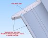
That said there are huge advantages to using Catia. Their sketcher i.e. 2D sketching for part body creation is insanely fleshed out. Geomagic Design's by comparison is less so. However its worth pointing out that I can replicate the same sketches by planning ahead and using constraints to join sketch segments. What I mean by this is the following: in Catia one can create planes, line and points as reference items while in sketch mode. On top of that the sketcher allows one to create a continuous sketch containing both lines and arcs. This makes sketch creation a relatively simple affair, albeit in a very complicated UI with a complicated methodology. In Geomagic Design all reference items must be created beforehand. In terms of sketching, a sketch must be drawn as separate segments to be constrained. The outcome is the same though.

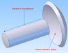
Switching between part design and shape (surface) design is seamless and this opens the door to modelling some very complex shapes. While Catia's surface design workspace doesn't offer as many options as, say, Rhino it doesn't need to and has more than enough features to get the job done. Particularly since it goes hand-in-hand with the part design workspace. Geomagic Design's surface workspace isn't worth mentioning, in my opinion. The few times I played around with it it didn't live up to expectations.

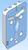
The part design workspace is where the Catia blows Geomagic Design away in terms of features and capability. There are a bonkers amount of options available for everything, from extrusions to chamfering/filleting to shelling... you name it, Catia can do it. That said I personally find a lot of the options to be novelties meaning I can't see me using the bulk of them in my original line of work i.e. product/mould design of the plastics industry. Its unlikely that I'll need them in my current line of work either, although its only been a month and a half.

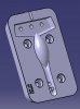
Interesting to note is that one can create two (or more) separate part bodies in one part workspace and use them in boolean operations in that one workspace. In Geomagic Design one would need to import a completely separate part for a boolean operation. This not necessarily a bad thing though as it makes editing the separate parts far easier. With Catia's complicated user interface and design tree it is very easy to lose track of what's what.

Its pretty much the same story for assemblies and drawings too. The capabilities on offer far exceed those of Geomagic Design. But I stress again: the bulk of the features are most likely not going to be needed.

...
 

bigseb

Alibre Super User
Creo is quite a different story. Outwardly it certainly appears more user friendly than Catia. The user interface is much closer to your standard parametric solid-modellor (and with a more modern feel, if that matters). What gets me about Creo is that despite all factors pointing it in the right direction it has a clunky feel to it. It is immensely powerful, no doubt about that (although no where near the functionality of Catia) but it all seems to fall apart when it comes to usability. Geomagic Design is, again, far simpler to use. I'll list a few examples.

Firstly, navigation is much easier in Geomagic Design. Zooming, panning and rotating the model can be done with one hand while Creo requires using a keyboard-mouse combination.

I also really dislike Creo's auto-dimensioning. Every single sketch has dimensions automatically added to it. Yes, these can be edited and replaced but not deleted. So drawing a large complex sketch and then adding new dimensions to correctly place it is often just not possible due to already existing dimensions be placed by the software that put the sketch in an over-defined state. The software doesn't allow you to proceed in an over-defined state so ultimately you have to delete segments and redraw them separately. In this case Geomagic Design is better than Creo.

Creo's sketch abilities are also not as fleshed out as Catia's, or Geomagic Design's, for that matter. I find sketching in Geomagic Design is much easier and sketches are hugely more customizable for that matter, provided the sketch is properly constrained.

In part design things start to look better. Creo also allows one to switch between solids and surfaces, although not on the level of Catia. This has huge advantages, not just in terms of part design but also when it comes to the machining side of things.

At the same time Creo doesn't seems to have boolean functions as one might see them in other software. This is odd as it is such useful function. Yes, Creo has something similar but its difficult to find (for a new user) and is a complicated, multi-step method. Once again, I find Geomagic Design's method to be far simpler to use. This 'multi-steppedness' is something you'll find a lot in Creo, from offsetting lines in sketch mode to patterning feature. It gets really tedious.

Assemblies and drawings leave a similar impression. Plenty of potential but hobbled a clunky interface and some rather poor choices as far as operation goes. Overall I am not impressed by Creo. If was going to spend a ton of money on a top-of-the-line CAD software then I would mostly likely go with Catia. Despite its awkwardness it still shines over Creo.

...
 

bigseb

Alibre Super User
So where does this leave Geomagic Design? Well, thats a good question. In my opinion Geomagic Design is still an amazing software, not just in terms of what one pays for it but also for what it does. All the basics are there. And there is a so-called workaround for everything else. For the record, I don't like the term 'workaround' when it comes to using Geomagic Design. Geomagic Design is its own software with its own functionality and just because it doesn't do something like Solidworks (the software it is most often compared too) or another software doesn't make it a workaround. Different software, different functionality. I am very impressed by the overall usabiltity of Geomagic Design. However, it is not flawless. Here are some of my gripes (these have been mentioned several times over the years.... so nothing new):

1) Filleting is unstable. Very often a fillet just won't work in Geomagic Design but will work fine in other software. While I understand that fillets may not work due to mathematical limitations it is strange that a fillet works in one software but not another. I also notice that certain filleting scenarios result in 'disappearing faces'. These are not just visual flaws but are carried over to exported models too. Similar results have been observed using the chamfer tool.


2) Extruding to a concave face is not possible as demonstrated in the screenshot. This really needs to sorted out as it is, in my opinion, a very basic requirement. I would suggest that the function is also modified to allow for multiple 'extrude to' surfaces to be selected (say two faces at an angle to each other and the fillet between the two)


3) Lofting with a centre-line! I know I am not the only one suggesting this. The current lofting tool is not great and lofting with guide curves is just not worth the pain. There needs to be an easier way to do lofts.

...
 

Attachments

  • Capture01.JPG
    Capture01.JPG
    34.1 KB · Views: 14
  • Capture02.JPG
    Capture02.JPG
    36.7 KB · Views: 15

bigseb

Alibre Super User
4) Sweeps should allow for twisting along the guide curve.

5) Patterning (this is a biggie!): too often I can pattern features but not the fillets and chamfers associated with those features. This is a big issue in my books and costs me a lot of time filleting/chamfering iterations of a patterned feature. Examples include gears and impellers where teeth/blades could be patterned but the chamfers/fillets on those teeth/blades could not, to multi-cavity moulds where runner systems needed to be individually filleted due to this fault with the patterning tool.

6) No sketching in the hole feature tool. Yes we can create a hole feature, close it, then open the associated sketch and sketch as needed. That's an extra step I could do without though. I should add that it knocks the socks off Catia's hole feature tool.

7) Importing meshes doesn't always work too well. Not a major issue but would have been useful here and there.

8 ) No ability to change settings for design tree. Personally I would prefer to have all design tree folders closed as default. I would also like to be able to add folders, particularly under the 'features' section. This would allow me to group associated features. Example: when designing a mould plate I would like to create folders for water channels, fastener holes, cavities, runners, etc with each folder containing the sketches, features, etc of that particular element of the plate.

9) I would like to see the surface tool fleshed out a bit to be of real value. Basic functions of surface creation would be fantastic, eg. extrude, sweep and loft. And naturally these should be fully parametric and work hand-in-hand with the solid workspace. That would elevate Geomagic Design to awesome heights, in my opinion.

10) Errors on exporting. Every now and then something happens that leaves me a bit red-faced. Here is an example. This is a cavity insert designed for a client in Geomagic Design:


This is how it looks when imported into another software:


I don't know why Geomagic Design does this but it should be sorted out. For interests sake, when this happens I do the following: I import the stp file from Geomagic Design into Moi and then export directly as stp again (making no changes whatsoever to the model). An extra step that I could do without.

11) The RAM issue. Geomagic Design holds onto RAM like a pitbull onto a bone. And the only way to clear processes is to shut Geomagic Design down completely and restart.

These are my top gripes. There are also things about Geomagic Design that I really love. Its has a very fresh interface that is a delight to work with. Seriously, go create a simple sketch in Catia or Creo (even Solidworks or SolidEdge) and extrude it and see how many hoops you need to jump through. The Geomagic Design direct editing tools are the awesome too. Out of the newer additions to the software this is easily one of the best. The integrated scanner workspace is a great idea although I haven't had a chance to work with it personally. Overall I have been using Geomagic Design for the last 5 years for all my product and injection/blow mould design and it has done a great job and the resultant output is equal to that of any other software. I realize that many have had a different experience and that's a pity but I doubt that moving to a different package is the answer (as should be evident by all I have written above). I will stick with Geomagic Design and be happy knowing that I have a great bit of software at my disposal.

Anyway I hope that this was useful/informative for my fellow Geomagic Design users. Obviously other users may have other opinions. I use Geomagic Design for a specific purpose and there are elements I just don't bother with so I can't comment on them. I also really hope that someone from Geomagic/3D Systems read this and takes note, particularly of my suggestions. It would be beneficial for them to be more involved 'on a shop level' and certainly help in instilling confidence in the product. And yes, I will email this to them too...
 

Attachments

  • Capture03.JPG
    Capture03.JPG
    27.6 KB · Views: 15
  • Capture04.JPG
    Capture04.JPG
    29.8 KB · Views: 12

aptivaboy

Senior Member
A very well written discussion and analysis.

A lot of what you've written have been my major gripes, as well, but including instability and crashing. I concur on the filleting and chamfering issues, and especially the import/export issues. Sweeps and lofts need to cleaned up. Its gotten to whenever I need to do a sweep or a loft I often go to MOI as a matter of course. MOI does things so easily. I really want Geomagic to play as nicely.

Bob
 

kedark

New Member
Thank you for your insightful analysis and suggestions, bigseb. Surely, it helps us when we hear from users like you who have not only been using Geomagic Design for quite some time, but also other software. I have noted down your suggestions and will get back to you in case I need any additional details on your suggestions. Thanks.

Kedar
 

bigseb

Alibre Super User
aptivaboy said:
A lot of what you've written have been my major gripes, as well, but including instability and crashing...
I have read all the threads about Geomagic Design crashing. I can't quite relate as my crashes are few and far between. The fact that I have them so seldom while others have them so often leads me to believe that it is either user-related or hardware-related. My opinion, I may be wrong...
 

TimoCAD

Senior Member
Hi bigseb, hi kedark,

I'm also a experienced CATIAV5 and NX9.5 User and am having GD for private use.
I can completely understand what bigseb is talking about. GD is not far from beeing a great product, but its about some small things that have to be done.

At first having boolean functions in the part workspace is necessary together with a folder function to group features.
If we have this we need not only a project to sketch, also a intesection to sketch of faces, curves, edges and bodies.
Projecting curves in faces and surfaces would be also necessary for having 3D Sweeps.

And the next step would be to integrate simple surface design features like we habe them for solid design. Extrude, rotate, sweep and lofting. Also fillets and chamfers are really important for that.
We need this for doing complex deep drawed parts and parting surfaces for molding.

This are some basic steps for getting GD to the next level, closer to the big CAD softwares.
And I know many engineers who like to have a CAD system for home or personal business usw, this should be the aimed group of customers of GD at first.
 

TimoCAD

Senior Member
...forgot something:

- please do something about this helix bug. If I want to draw a technical spring I need to cut the ends to the right shape and not 0.1mm off the desired shape, you'll know what I mean.
- we need an additional Export Format: *.jt (XT-Brep) important for automotive suppliers.
 

aptivaboy

Senior Member
I have read all the threads about Geomagic Design crashing. I can't quite relate as my crashes are few and far between. The fact that I have them so seldom while others have them so often leads me to believe that it is either user-related or hardware-related. My opinion, I may be wrong...

Since I upgraded to a new PC and V.17, the instability has been reduced markedly. I suspect Geomagic didn't play well with the graphics and memory combination on the old machine, for whatever reason. With a more powerful video card and 16GB of RAM, there are very, very few issues.

The ability to get Keyshot with the upgrade was also wonderful, and the Keyshot licensing was not an issue - it just installed and was instantly usable, unlike prior instances where getting a license key was... Problematic. Congrats to Geomagic on this.

A very nice rundown of Geomagic's pros and cons, Seb, and a great review. After testing other CAD programs, I decided to stay with Geomagic for one more upgrade and maintenance cycle. I still can't find anything else that is as intuitive nor as easy to learn. I truly hope the current owners really make a serious effort to upgrade the program. Its so good compared to the competition. One area I'd like to see them reexamine is the home hobbyist, one of the markets that the original Alibre Design targeted and marketed to.

Bob
 

RCH_Projects

Alibre Super User
As a CAD/design/engineering/everything neophyte (in 2008) I was looking for something "I" could use and manage. I tried the trials of the big name software as well as Alibre.

Just trying to use the interfaces of the big name brands (selecting, moving, rotating, creating, editing, etc.) was daunting. Alibre was like finding a user interface designed for humanity.
The bang for the price made it a no-brainer (simulation aside). I'm off maintenance for financial reasons but I hope they keep plugging away to improve the software/value.
 

3dcad.fi

Member
Glad to read other users appreciate this fine piece of software too. And even more glad to notice we have developers participating on the forum!

My requests currently would be (in addition to bigsep's & others lists):

1. 3D systems, please let Geomagic Design users contribute in development process. Tell us what are your plans, what is going on and what is coming up! Let us give feedback and vote for priority on new features.
2. Copy/move sketch from plane to another WITH constraints and dimensions, choose to follow original sketch or create 'stand alone'
3. Built-in patterns for hole tool (like 'shape tool' has). As I have a lot of hole groups in my furniture pieces, I would love to have only one feature / place for each holegroup where to modify.
4. Sketch rectangle by midpoint
5. Bug fixes on assembly interdesign parts parametric behaviour with different configurations
6. More types of constraints in assembly - 1 constraint for part should be enough, anything more is waste of time.
7. Wireframe view with only visible edges to all workspaces
8. 3D measurement tool for creating visible dimensioning to 3D model. I mean multiple visible dimensions to be able to create quick manufacturing drawing directly in 3D workspace.
9. Saved views, for creating drawings like views with sectioning, dimensions, etc. directly in 3D workspace and save them for quick access / print.
10. Maintain feature colors in Keyshot export, we should be able to assign different material (paint color) to different colored features.

What I currently keep in highest value compared to other low price 3d cads:
- Super easy parametric design with global parameter possibility
- Configurations (bugs concerning assemblies and drawings should be fixed though)
- Stability, no crashes since v14 (apart from windows or hardware related problems)
- Ease of use and intuitive design with automatic updates
- Already enough main features and tools, needs only small improvements to meet basic requirements of design process.

@bigsep - concerning filleting patterns/mirrors, I'm creating first pattern/mirror of extrude, then another pattern/mirror for fillets. I have explained this 'workaround' to myself so that 'how can you make fillet to something that doesn't exist, you need to first create extrudes then fillets'. It's faster way than manually clicking edges and if using parameter in fillet pattern, modifications doesn't need additional steps.
I did some testing to actually remember what was the problem, I couldn't make it fail anymore. Version 2015.0.0 seems to create fillets without problems within same pattern/mirror as extrusion.
Actually I remember this not being issue in older versions, then it begin to fail at some point, now it works again (can't remember for sure though).

@kedark Is this fillet patterning issue fixed in recent updates?


//rami
 

Attachments

  • GD fillet.PNG
    GD fillet.PNG
    119.2 KB · Views: 26

simonb65

Alibre Super User
3dcad.fi said:
1. 3D systems, please let Geomagic Design users contribute in development process. Tell us what are your plans, what is going on and what is coming up! Let us give feedback and vote for priority on new features.

+1. Geomagic, this is the most efficient and direct market research you will ever get !

3dcad.fi said:
4. Sketch rectangle by midpoint

+1

3dcad.fi said:
9. Saved views

You can already do this ! Create a custom view then use it to create the 2D drawing or shaded view (with section if needed). I use it extensively for getting the right isometric, non-standard but in some cases a more clearer, view.

3dcad.fi said:
10. Maintain feature colors in Keyshot export, we should be able to assign different material (paint color) to different colored features.

I save all my parts with a material and colour code in the part name, then use the Material Template feature of Keyshot to auto assign the texture based on those codes. It's a work around, but save a bunch of time. Would be nice to automatically pick up the material and colour in keyshot from the part properties though.

Ultimate goal would be to integrate the renderer into Geomagic Design completely rather than being a seperate tool, then you could do more with part properties and metadata.
 

Jimpulse

Alibre Super User
3dcad.fi wrote:
4. Sketch rectangle by midpoint

Does the center located Rectangle function of the Shapes tool not work for you?

(I acknowledge that LOCATING the entity of a Shapes tool is a little awkward)
 

JST

Alibre Super User
I see what you mean, but are we not being very fussy?

It appears to me that the very fact that GM can be discussed alongside Catia without everyone just falling down laughing at the very idea is a tribute to the fact that it is a very nice program.

And, all the complaints we have about it are also a tribute to the fact that it is already so good that we EXPECT that these things shouldn't be issues. If it were not at the level it is, we'd consider the "problems" to be just expected, "normal" for low end CAD systems.

Catia is stupidly powerful, which it should be after something like 30 years of development. And given what it was made for. That does not make GM unsatisfactory.

Personally, I find GM to be way better than nearly anything else in the same category price-wise. SWX has both better and worse features, but costs considerably more, for instance. I don't really like it, and I have used it. I have access to a seat of SWX, and I avoid it in favor of GM whenever possible.

bigseb said:
..........
1) Filleting is unstable. Very often a fillet just won't work in Geomagic Design but will work fine in other software. ........

2) Extruding to a concave face is not possible as demonstrated in the screenshot.
................
...

Yes, those.

Also

Need a direct UNDO command from the full assembly constraint dialog. I know quick has it, but the main does not.

Need a conical constraint.... constrain cones with inside or outside tangent. Right now even a flathead screw has to use a workaround method.

Need constraints to "non-geometric" faces, ones generated from a spline, etc. Now it is totally a visual thing only.... No constraints of any use work with it..... To be quite fair, GM may not be alone in that, it's a tough problem.

Need an "approximate constraint". One analogous to a real world pin in a hole, or bolt through a hole.... constrained to be within a square or circular area in a plane around the actual point.

Bug: tangent is unstable, I have demonstrated and documented tangents that actually are only tangent on "non-physical extensions" of the surfaces, WAY OUTSIDE the actual model surfaces. THAT is really unacceptable.

The other problems I have with GM at present are pretty much just related to 3DS company policy, and not the program. I'd have liked the "free upgrade from Elements to Design" to have been cheaper than just buying a new seat of design.... Unfortunately it isn't, because I am not using, and can't use, the latest version, but that's the only one they will upgrade me to.
 

NateLiquidGravity

Alibre Super User
Not sure if this is the place, but since we are listing and have gotten a response from Geomagic personnel - here is my list in no specific order.

Code:
bug: multiple instances of edit text fields dialog

bug: progress bar often not shown during entire operation (save and load).

bug: arrows in drawings don't fill properly.

bug: dimensions not updating. they are clinging to nodes floating in the middle of nowhere.

bug: angle constraint freaks out when over 180° or when negative.

feature: rotate views (align selected edge of part horizontal/vertical)

feature: baseline dimensioning (select a baseline point/edge or side of existing dimension and then add dimensions using that baseline as the starting end- center dimensions and space like "reposition dimensions" - command stays active til exited)

feature: continuous dimensioning (select a point/edge or side of existing dimension and then next end of dimension using previous end as start of new - center dimensions and keep aligned - command stays active til exited)

feature: "show reference geometry" and "show part in explorer" should work on the reference geometry of a part

feature: view transitions in "standard views creation" to make it easy to follow which way the part is.

feature: a midline constraint selecting two lines should automatically place a node with a midline constraint to both lines.

feature: arc length/circumference dimensions. for sketches and drawings with equation capabilities.

feature: copy views

feature: merge/ swap/ copy sheets in and between drawing files

feature: select more than one sheet at a time to make a pdf of. each sheets' pdf page should be made the same size as its template/sheet properties.

feature: reproject views. sheet icons (in dialog and drawing explorer) should be red if views on them need reprojecting. in reproject view dialog sheets only sheets needing reprojection should be expanded to show views.

feature: stack fractions vertically and diagonally.

feature: change drawing view configurations after views are made.

feature: isometric dimensions true size when measuring parralel to x,y, and z directions of model.

feature: variable radius bend sheet metal flanges. As seen when using the lofted sheetmetal feature.

feature: multi-top-level-parent-file project copy/save/rename. Meaning a project with more than 1 drawing file or top level assembly. Currently this requires more than 1 save all as that creates duplicates.
 

albie0803

Alibre Super User
My desire: to be able to put a thread on a stepped shaft that isn't right on the end, then to be able to put a keyway through it and then have it show correctly on a drawing. Related to this is a thread on the end of a hollow shaft and have it show correctly on a drawing.

I work with gears, shafts and gearboxes and not being able to add a bearing locknut thread and tabwasher slot in from the end of a shaft and have them show correctly on the drawing has been so frustrating over the years.

Fix the diameter dimension tool: Before I started with GD/Alibre I was using ProDesktop Express and it had a Diameter dimensioning tool which worked across keyways. You could section a gear through the keyway, select the Dia Dim tool and click on the bore line and it would report the true diameter of the hole, not the length to the bottom of the keyway. There are many other instances where this would be useful.

ProD also had a Circular Hole Pattern centreline tool: In drawing mode, select 3 or more holes on a view and it would allow you to put in a PCD centreline with 1 click without having to have created them using the pattern tool. Good for non equispaced holes that are still on the same PCD.

1 last one: Add to the hole thread tables default countersink/counterbore dimensions for common sizes that can be easily edited. Whip up a BUILT IN hole table editor for easy alterations and block imports along the lines of this: WertEditor
 
albie0803 said:
1 last one: Add to the hole thread tables default countersink/counterbore dimensions for common sizes that can be easily edited.
There is a tool for this. The problem is that it is undocumented and barely known. It is called the Hole Preset System. The file is alibre_unicode.hps and is located (once created) in the C:\Users\Your User Name\AppData\Roaming\Alibre Design\Your GMD User Name\ directory (as opposed to the more usual directory). If you search through the forum here or my area over at GrabCAD (http//www.GrabCAD.com), you will find a spreadsheet set-up to generate the alibre_unicode.hps file.

Cautions: (1) You have to create a Preset hole using the Hole Tool to establish a "link" between GMD and alibre_unicode.hps. (2) This otherwise wonderful tool has not been "polished" anywhere near the degree to which it should. All definitions end up in a single pull-down list that becomes very hard to navigate in an exceptionally short time (i.e. "count" of Hole Presets)! (3) It only allows you to "blend" two features into a Preset which means that spotface or counterbore holes are "short" the chamfer required to clear the underhead fillet.

Even with these shortcomings, this is a start on a very powerful tool!
 
Top