What's new

Geometry gets corrupted. Why?

Elrick

Senior Member
I think it might be related to the last update because I didnt notice it before that. Some parts appears to be fine but distorted in assemblies. Does anyone know why this happens and how to prevent it? Can it be fixed or is backup my only hope? Please help. Im tired of this :(
 

Attachments

  • Strange geom 1.png
    Strange geom 1.png
    516.4 KB · Views: 21
  • Strange geom 2.png
    Strange geom 2.png
    269.3 KB · Views: 16
  • Strange geom 3.png
    Strange geom 3.png
    311.9 KB · Views: 18

Elrick

Senior Member
First time I noticed it was when I made this pdf (07 - 16)...
 

Attachments

  • Strange geom 4.png
    Strange geom 4.png
    1,002.3 KB · Views: 46

bigseb

Alibre Super User
I have this quite a lot too. Its a real PITA. Generally this happens when GD doesn't like something I'm doing. For example: I add a fillet to a part and corrupted faces (sometimes faces just disappear altogether). Now if I remove the fillet then its back to normal. Add the fillet and its corrupted again. I think (correct me if I'm wrong) that this happens when GD can't properly compute a process (like a fillet or chamfer or boolean operation, whatever) so reducing the fillet/chamfer size sometimes helps. Or moving the boolean operation up or down the tree; shifting the order of the processes.

Either way, you end not working the way you want. Often I'm left with a part a 3mm fillet works but the (desired) 4mm fillet doesn't. I could mad about this but to be honest I sometimes wonder if this isn't shortfall of all cad systems too. Surely there is a limit what they can put out...
 

Elrick

Senior Member
Usually I would look for the problem but this time it werent an error from die tree. I didnt touch the parts. I believe this was caused by the update. I mostly try to apply all the advice I find here on the forum from you guys. And learning from mistakes. This feels colossal. The assembly files got corrupted it appears. I will replace it with an older assembly and see what happens. Stuff like this happened before. Also after an update. Its just a bit discouraging after all the bad luck weve been having lately. As you can see its a very large assembly. Months' time and effort. In times like these I wish Ralph knew about a box I should tick somewhere to release the data from this technical curse. lol Hopefully when I replace the main assembly there will be "magic"!
 

Elrick

Senior Member
Nope. Went through my backup and the same parts seems to have the same problem. I know for sure it didnt have any malfunctions back then. So im pretty sure it has to be the update. One problem down, a bigger one pops up. But youre probably right Sebastian. All software have their advantages and weaknesses.
 

H-L-Smith

Senior Member
Elrick said:
. . . I didnt touch the parts. . . . Stuff like this happened before. Also after an update. . . . . Hopefully when I replace the main assembly there will be "magic"!

Elrick said:
Nope. Went through my backup and the same parts seems to have the same problem. I know for sure it didnt have any malfunctions back then. So im pretty sure it has to be the update. .

So, it sounds like you are saying similar things happened in versions prior to GMD 16? For example, maybe 2012 came out and the problem(s) appeared, but then disappeared as new builds and bug fixes were completed for 2012 then appeared reappeared again when 2014 was first released? Maybe I just didn't understand what you said.

Sorry for your troubles, Elrick. You obviously got a very complex project and it's always great to see your work. I can appreciate how frustrating it must be to have these issues occur when you think things are all buttoned up and finished.

Cheers,
 

Elrick

Senior Member
H-L-Smith said:
So, it sounds like you are saying similar things happened in versions prior to GMD 16?
Thanks for the good words Lonnie! When it previously happened I had to fix this my self. But it were only one major part. When it happened I scrapped the file and continued from backup. One thing I regularly do is export finished designs and import it again. The file I use the most is a ACIS R23 file. Cos the part comes back as one. Making the assembly tree shorter. Saving plenty space and time with backup. [Making backup of this whole assembly takes less than 5 Seconds (now only 3GB!)]. So maybe that could be a lead to this problem. Just a guess. Can one of you perhaps recommend a better file other than this one and a stp? From recent experience Ive come to trust igs? The parts you see in the first post were exported/imported as .sat files.

Do any of you gents here know topics on the forum related to file transfer glitches? What else might have caused this?

Any help thanks!

Regards,
 

TylerDurden

Alibre Super User
I've a hunch it is related to floating-point operations, but I've no hard data... brief tests I've made on lofts that failed/succeeded were only altered by a few decimals.

If you have a GM .prt file of the rectangular frame (shown in the pic) made in GM2014 v15 or earlier, I'd be happy to open it here and post results.
 

Elrick

Senior Member
Thanks Tyler. I will see what I can dig up at work on monday. There might be a slight problem cos since the thumbnail explorer crashing bug were fixed I opened a lot of the files with the new version and saved them again to fix their blank thumbnails. If that might have "interfered" with the "floating-point operations" of the files. What is this btw?
 

Elrick

Senior Member
Over here youl see it looked a lot more clean. Pdf of a few months back. Things keep changing/improving but with crashing too makes it hard to cope. I need a quick solution :)
 

Attachments

  • Online help.png
    Online help.png
    760.3 KB · Views: 20

Elrick

Senior Member
The original part.

https://www.dropbox.com/s/fhggn5yfchf6e ... %29.AD_PRT

When I used the "regenerate all" and "Generate to last figure" function on another corrupted part it helped to rid of this problem. But Im not getting the same results on other original parts. (parts originally made in GMD before exported and imported back). Finding the original parts corrupted should prove that the problem arent related to the export features?
 

TylerDurden

Alibre Super User
Howdy,

The rar files seem to open without issue on my setup:


Regarding floating point... it is how computers do fancy math. I barely understand the concept, but rounding must occur in many cases and resulting differences might interfere with generation of solids. http://en.wikipedia.org/wiki/Floating_p ... y_problems

I'm not saying this is the root of the issue, but might play some part.
 

Attachments

  • Frame2B.jpg
    Frame2B.jpg
    163.4 KB · Views: 4
  • Frame2C.jpg
    Frame2C.jpg
    148.5 KB · Views: 2
  • SunroofOpen.jpg
    SunroofOpen.jpg
    153.2 KB · Views: 5

H-L-Smith

Senior Member
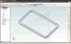
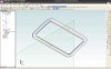
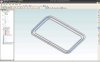
I haven't uploaded your file, but did wonder if you can actually select those errant edges and surfaces in the 3 parts you first posted. In other words, are the edges, surfaces, etc., really in the 3-space location where they are rendered or is the issue that the display library can't handle the geometry for some reason and paints them in the wrong place?

Said another way, the actual part geometry may be OK, but the 3D rendering of them fails for some reason. I've seen some strange things like that occur in other 3D software when you get local surface normals reversed on one or two segments of a part and the rendering engine can't handle it.

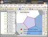
When you select the wonky things in the Design Explorer, does every portion of it change color to show selection or just some parts of it?

Cheers,
 

Elrick

Senior Member
Thanks for coming back Tyler! What version do you use now? My current version is: 16,0,1,16490 . I thought the latest wouldve been better since it fixed the thumbnail bug. The thumbnails are very helpful when youre searching for specific parts in a big bunch. Otherwise I will have to revert back to annoying explorer crashes in exchange for cleaner visuals? I will jump to that tomorrow and give some feedback.

@Lonnie, Yes. That yellow you see in the screenshots are surfaces I selected. There actually are meshes. It looks like lofts gone really bad. And similar to bigseb (sometimes faces just disappear altogether). You see some surfaces from one angle and becomes transparent on other. (Might be that the solids arent "water tight"?) I refer to this as corrupted since I first saw it when I exported parts, in particular the middle one on the first post. But that were exported files. The actual parts werent affected at all. Now they are. The main and most important parts. I hope that this is just rendering problems and rolling back to previous version will solve this! Cheers

Im a bit curious to know what is the term used for the camera position when it falls perpendicular between the screen and the chosen sketch plane? Any of you know such?
 

TylerDurden

Alibre Super User
Howdy,

I'm using GDE 2014 v15, see my sig for setup details.

Maybe it would be helpful to also upload/post some .sat files to examine.

I understand the benefit of exporting and importing of solids, but it may be that precision and surface integrity is literally lost in translation.


Not sure if you mean a camera viewing normal to a surface or 90 degrees to normal. If the sketch figures are visible, I'd say normal.
 

Elrick

Senior Member
TylerDurden said:
Maybe it would be helpful to also upload/post some .sat files to examine.

The rar file should be an assembly file consisting of imported .sat files. Unless you mean before it were exported?

Lets take the computer screen as the camera eye/lens. A planar surface. When the plane you draw on are parralel to the pc screen. Two parralel planar surfaces that never intersects when their surface area are infinute ( the position the screen and the plane takes when you activate 2d sketch )Its got something to do with the "project to sketch" tool.

I rolled back to version 15.0.1.15081 and all the parts appears to be normal again. Added I opened back-up four weeks old since the older version doesnt want to open updated files. Hopefully the files drawn since wouldnt give trouble when I try to export/import on our workstation with latest version. So Im almost entirely sure the update caused all this trouble. And it could be related to visuals since the thumbnail crashes are too. Im just very relieved to see the back-up working like it should and that I dont have to waste more time fixing finished parts and assemblies again. Crashes much less troublesome than these techni spider webs. I will keep this topic updated on the matter.

Im working on a plan to get rid of all the lofting edges. It seems impossible to finish these parts in a single loft with GMD. One thing I saw on Rapid Works is that your guide curves doesnt need to begin & end on the first and last sketch. The lofts are controlled by the guide curves as much as the sketches. Think this is surfaces only. You probably can give them thickness later. It might help a lot in GMD! Something I thought about before when bussy drawing. Another thing I liked and also thought about before were to give extrusions the ability to go both ways at the same time. It wouldve saved some time in GMD! Since I became more involved in mesh software and saw what it can do I came to believe you can export surfaces from GMD and fill the gaps between the lofted surfaces in other software to make the surface one. Giving it thickness again later? So far I had some promising results with Mesh mixer. But the surface quality cant be compared to the smooth surfaces made in GMD when it returns. It comes back as one but looking worse. Any one of you tried to do something similar before? Without the loft edges the drawings will lose some perspective but smoother surfaces are what Im after. Deviding parts into more than one loft causes many problems but it seems like its the only way for GMD? If GMD and Rapid Works are both owned by 3ds why cant these really handy functions from RW be implemented into GMD now?
 

TylerDurden

Alibre Super User
WRT camera/view, I'd use the language "camera (or view) facing the surface normal". To align while in sketch mode, AD/GD has a handy tool:
 

Attachments

  • OrientToSketchPlane.jpg
    OrientToSketchPlane.jpg
    81.6 KB · Views: 13

Elrick

Senior Member
Handy in deed! Especially when you need to draw on the other side of a plane. Thanks for sharing the term. Not something Im familiar with. It sounds very programmatic and mathematical. Very interesting!
 

TylerDurden

Alibre Super User
"Orient to sketch plane" will flip with each press... similarly, "orient to isometric" will cycle through the angles with each press. Very, very handy.

Elrick said:
Another thing I liked and also thought about before were to give extrusions the ability to go both ways at the same time.
Maybe extrude "Mid Plane"?
 

Attachments

  • midplaneExtrude.jpg
    midplaneExtrude.jpg
    164.6 KB · Views: 6
Top