What's new

Gridfinity bins, sweep cut and linear pattern issues

kkio

New Member
Hiya folks,

I've been trying to recreate the gridfinity bin geometry to get a bit more familiar with Alibre. Creating a single base is simple enough but I have a few things I've been struggling with.

1) For the overall base profile, I create a profile and sweep cut that around an extruded block. I had to create a path for a single side and then feature pattern that around the remaining sides. Is there a way to do this with a single path/no pattern?
1692548331259.png

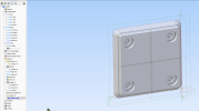
2) One of the aspects of the gridfinity bins is that you can tile the bases to achieve larger bin sizes. When I try to linear pattern I get cut off portions due to it repeating my sweep cuts. Is there a way around this problem?
1692548498653.png

I've tried to use a linear topology pattern instead but I get the following (PTRN_BAD_BUMP) error:
1692548551137.png

Any insights would be much appreciated! Thank you.
 

Attachments

  • 1692548244173.png
    1692548244173.png
    622.1 KB · Views: 3
  • gf_base.zip
    87.6 KB · Views: 1

DavidJ

Administrator
Staff member
Wouldn't it make more sense to pattern the base in an ASSEMBLY, rather than in the part? No problem then with your cut interfering with other instances.

It might help if you tell us what a 'gridfinity bin' is.

You can make a closed loop path for a sweep, though probably simpler ways to make the part. I would probably extrude rectangle to thickness of the sloped portion, fillet corners, then chamfer to give the slopes. Next extrude from the smaller face to give the parallel portion. Then either add holes, and final small chamfer - order not critical.
 

kkio

New Member
Wouldn't it make more sense to pattern the base in an ASSEMBLY, rather than in the part? No problem then with your cut interfering with other instances.

It might help if you tell us what a 'gridfinity bin' is.

You can make a closed loop path for a sweep, though probably simpler ways to make the part. I would probably extrude rectangle to thickness of the sloped portion, fillet corners, then chamfer to give the slopes. Next extrude from the smaller face to give the parallel portion. Then either add holes, and final small chamfer - order not critical.
Thanks for your reply! Like Nate shared above, gridfinity is just a design spec for a modular organization system. You can create bins of varying sizes like this:
1692575863056.png

You'll notice that they all have the same base, just in different counts.

I actually did make my initial attempt in the way that you describe (with filleted corners and chamfers edges) but I tried sweeping a profile since I was also having different issues patterning the base there.

If I were to follow your suggestion and make it an assembly, could I still make it in such a way that I could extrude out the top portion of the bin and it could dynamically resize based on a count of how many units long/wide I want?
 

bolsover

Senior Member
I played about with gridfinity a year or so back..
I came up with the attached for boxes.
I didn't acually print many boxes - seemed to waste a lot of fillament.

In the equation editor you only have to chnage the Variables with the names:
A_INPUT_X_COUNT, A_INPUT_Y_COUNT and A_ INPUT_Z_HEIGHT

Everything else is calculated.
 

Attachments

  • BoxBase.AD_PRT
    4.6 MB · Views: 8
Top