What's new

Helical gears creation

Gregory

Member
Good morning.

I need to make accurate involute helical gears in Alibre Atom3D.

When i construct gear cutout as always and make a straight gear they mesh perfectly.

When i use the same sketch and make a helical cut, with a helical pitch calculated from a formula: "reference circle diameter" / tan ( "helical angle" ), my helical gears mesh perfectly only when i try to mesh gears with the same number of teeth. For example when i try to mesh gears with 32 and 48 teeth i get collisions, it seems like the helical angle is not the same, but i cant find where i make a mistake.

Attached are assembly with straight gears - showing correct meshing and helical gears showing collisions.

Any help appreciated!
 

Attachments

  • helical_gears_problem.AD_PKG
    1.5 MB · Views: 13
  • straight_gears_ok.AD_PKG
    1.1 MB · Views: 4

Gregory

Member
Another example, i tried to remade the healical gears by taking the gear profile straight from spur gears, still no luck.
 

Attachments

  • helical_gears_problem2.AD_PKG
    1,013.9 KB · Views: 2

bigseb

Alibre Super User
I looked at the attached files briefly. The only thing that immediately jumped at me was the interference of the top and bottem smallers gears with the middle one. Were the centres off maybe?
 

DavidJ

Administrator
Staff member
I'm not a gear specialist, but surely the helical angle (and hence the screw pitch if using a helical feature) will be same for all gears of a family (Module or DP and helical angle), so varying the pitch with reference circle size seems wrong. Perhaps check back with the source of the equation.

We do have one person on the forum who works with gears a lot - maybe he'll drop in and comment.
 

albie0803

Alibre Super User
I don't have a lot of tIme at the moment but 2 things:
The helical cut needs to be done on the normal - Helical Cut > Advanced > Profile Orientation > Normal
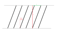
The helix angle calculation is wrong. If you roll a spur gear on a piece of paper you would get a row of vertical lines.
A helical gear will give angled lines, which is the Helix angle. You need to work out how far up the top the angled line goes for it to go sideways 1 circumference length. This distance is the pitch you want for 1 revolution of your helical cut.
See how that goes
 
Last edited:

Gregory

Member
Thank You for very informative replies.

I have changed the helix pitch calculation to "modulus * number_of_teeth * pi / tan( helical_angle)", and the helix profile orientation to "normal" per suggestions and it seems to work very good!
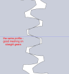
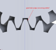
I still struggle with the tooth profile though. I create it with a B-spline for a perfect involute, and when i use the same profile for straight gears they mesh ok, when i use the helix tool with the same sketch there seems to be a gap between teeth. I need to investigate it further.

Again thank you all for help so far.

straight.png

helix.png
 

Attachments

  • gear test 4.AD_PKG
    2.5 MB · Views: 2

dwc

Alibre Super User
Are you sure that profile really works? If the teeth touch front and back, as they appear to, that is jammed and will not turn. You need some freedom behind the tooth.
Either your tooth profile or your inter-axle distance has a problem.
 

bigseb

Alibre Super User
Helical gear teeth are at an angle so your profile must be at an angle too or else it will be narrower.
 

albie0803

Alibre Super User
Your helix pitch calculation should be "modulus * number_of_teeth * pi / cos( helical_angle)", which will cause your gear to grow in the OD, which will affect your center distance. Normally a ratio is picked and the helix angle is adjusted to suit a desired center distance, or you adjust the addendum modification values to suit.
 

Gregory

Member
Your helix pitch calculation should be "modulus * number_of_teeth * pi / cos( helical_angle)"
It can't be right, because when you look at the gear from the side, you see a triange, and you dont use the longest side length in this calculation.

tan.png
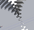
I succeeded in making the helical gears by using loft cut tool instead of helical cut tool. Seems like something is off with helical cut tool or my setting in this tool are somehow wrong. By using loft cut and making 3 profiles, one at the beginning, one in the middle and one at the end of the gear i managed to get a helical gear with perfect meshing at every section-cut along.

helix ok.png

Thanks to everyone for help, now i will try to make a fully parametric helical gear that actually updates!
 

Attachments

  • helix_teeth_ok.AD_PKG
    1,022.5 KB · Views: 4

Gregory

Member
Are you sure that profile really works? If the teeth touch front and back, as they appear to, that is jammed and will not turn. You need some freedom behind the tooth.
Either your tooth profile or your inter-axle distance has a problem.
in the case of touching both sides, i want to make a perfect profile, and adding backlash would be done later, when i am sure that the actual profile is ok.
 

albie0803

Alibre Super User
Sorry, you are right, I was confusing your measurement with the measurement of the PCD, which is "modulus * number_of_teeth * pi / cos( helical_angle)"
 
Top