You are using an out of date browser. It may not display this or other websites correctly.
You should upgrade or use an alternative browser.
You should upgrade or use an alternative browser.
Help Required for Traction Engine Wheel
- Thread starter Simonboyle08
- Start date
simonb65
Alibre Super User
Firstly, what version of Alibre have you got?
You need to model this as a solid.
1. Create 'half' a section of the part, then revolve extrude it (to get the blank).
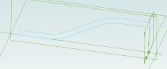
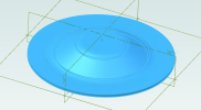
2. Extrude Cut a gap between the spokes.
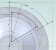
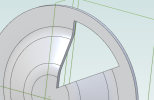
3. Circular pattern No 2.
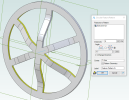
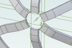
4. Extrude cut the centre hole.
5. Extrude Cut one of the rim holes.
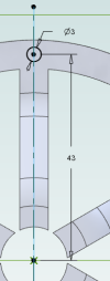
6. Circular pattern No 5.
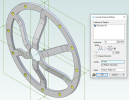
7. Add internal fillets.
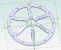
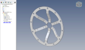
Alibre 'Expert' V24 part attached ...
You need to model this as a solid.
1. Create 'half' a section of the part, then revolve extrude it (to get the blank).


2. Extrude Cut a gap between the spokes.


3. Circular pattern No 2.

4. Extrude cut the centre hole.

5. Extrude Cut one of the rim holes.

6. Circular pattern No 5.

7. Add internal fillets.

Alibre 'Expert' V24 part attached ...
Attachments
Last edited:
Simonboyle08
Member
I am working with V24 ExpertFirstly, what version of Alibre have you got?
You need to model this as a solid.
1. Create 'half' a section of the part, then revolve extrude it (to get the blank).
2. Extrude Cut the gaps between the spokes.
3. Extrude cut the centre hole.
4. Extrude Cut one of the rim holes.
5. Circular pattern No 4.
Thank you Simon
simonb65
Alibre Super User
See my updated earlier post!I am working with V24 Expert
Simonboyle08
Member
Thank you SimonSee my updated earlier post!
I will give it a try
the help is much appreciated
HaroldL
Alibre Super User
@Simonboyle08 , This looks like it could be the start of an interesting project.
Why don't you post some images in the Media section when you're done with, or as you progress with, your traction engine.
Why don't you post some images in the Media section when you're done with, or as you progress with, your traction engine.
OTE_TheMissile
Alibre Super User
I could see this being modeled in Sheetmetal as well, that would allow you to flatten out the bends for layout purposes. Depends on what your role in this project's production is, if you're not making the thing and this is a part coming from someone else, the method described above would be fine for use in Assembly models.
You'd draw it almost opposite the way Simonb65 did in Sheetmetal, starting with the outside diameter and adding Flanges to build one of the finger spokes in the center, then repeat the process (or maybe Pattern, though I tend to avoid that kinda stuff in my Sheetmetal works) for the other five.
You'd draw it almost opposite the way Simonb65 did in Sheetmetal, starting with the outside diameter and adding Flanges to build one of the finger spokes in the center, then repeat the process (or maybe Pattern, though I tend to avoid that kinda stuff in my Sheetmetal works) for the other five.
simonb65
Alibre Super User
You wouldn't be able to flatten out the pattern as the spokes would have overlapping interference in the centre! I tried that before suggesting modelling as a solid.I could see this being modeled in Sheetmetal as well, that would allow you to flatten out the bends for layout purposes. Depends on what your role in this project's production is, if you're not making the thing and this is a part coming from someone else, the method described above would be fine for use in Assembly models.
You'd draw it almost opposite the way Simonb65 did in Sheetmetal, starting with the outside diameter and adding Flanges to build one of the finger spokes in the center, then repeat the process (or maybe Pattern, though I tend to avoid that kinda stuff in my Sheetmetal works) for the other five.
Although the single spoke and pattern would work in Sheet Metal! I tried as a complete wheel ... Doh!
Last edited:
OTE_TheMissile
Alibre Super User
I kinda assumed that's the reason there were small gaps between where all the spokes meet each other in the center, like as a flat layout those gaps would close up. Sheetmetal CAD was never my forte, despite how much I use it at work.
One thing that your method produces is curved bend lines, while the print in the OP appears to be regular straight bends. I dunno, I'm probably splitting hairs on this project for what OP needs it for. It's Monday morning and I'm still waiting for the caffeine to kick in
If it's not stamped, I'd hate to be the guy on the shop floor trying to form this thing up in a press or a sheetmetal brake
simonb65
Alibre Super User
True! There are many ways to create this to get it as per drawing. Mine was just a quick and 'dirty' example.One thing that your method produces is curved bend lines, while the print in the OP appears to be regular straight bends.
You could use the solid method to extrude a single spoke segment as per the first sketch, stamp cut a 60 degree pie from that, pattern that, then revolve cut the outer edge to make it round, then stamp cut the inside of the spokes. That would give the same result but with straight bend lines. That's the beauty of modelling, so many ways to solve these interesting problems.

