What's new

help with dimple / flange mending

bhowell

Member
First time here and need some help! I have created 6 support "rib" features in this plate (next to the 6 mounting holes). It appears that you can use the dimple tool in conjunction with a flange or curved corner. I was hoping that the ends of the support ribs would tie into the plates outside flange. Anyway to do this?.... boolean maybe? Attached is the part

Thanks, B
 

Attachments

  • push rod cover (ID 125).AD_SMP
    1 MB · Views: 39

RocketNut

Alibre Super User
Never mind I got it to down load. Also it took a long time before I could edit/look at the model (did any one else have this long wait also). I notice the file is a meg in size. Also I see you draw each cut & dimple which might be the reason the file so large. Couldn't you use the pattern tools? It would reduce the file size alot along with making model eazrer to edit in the future.
 

RocketNut

Alibre Super User
If you shoot me a drawing of the dimple along with is dim and what the spacing is. Also what size is the holes are along with there spacing. I will try to reproduce it for you. OH yes how deep is the part and what is the wall thickness.
 

bhowell

Member
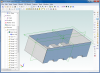
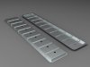
Wow Rocket, That would be great! I tried using the pattern tool last night to "pattern" the rib support dimples and i couldn't get it to work for me... must be doing something wrong. Anyway, the part itself is 27.5" x 5.55" with .75" rad. on the corners. There is a .5" lip around the edge. Circles are .4" dia. and 4.75" oc spacing. The circles are centered on the plate and the first one sits 2" off of the right side (measuring off of the outter lip edge). The depth of the part is .5" measuring from the bottom of the plate to the bottom of the .5" lip. As for the dimples.... they are simply there to add some strength to the part. I have drawn them .5" wide, .7" from center of hole to middle of rib dimple. The lenght ..??.. I was hoping that these "support rib dimples" would tie into the wall of the part on both ends. The height of the "support rib dimples" is not set... I'm flexible here. I drew them with a height of .3" Also, as far as producing the dimples, when prompted to select the 'sketch alignment' it does not matter if they are straight or rounded. Oh, and the wall thickness of the part is .0625" It would mean alot to me if you had some time to bust this out... Like I said early, I'm new to alibre and with a deadline looming to have this part made... what a help it would be. Thank you
 

bhowell

Member
Rocket, In thinking about this more... maybe the support ribs shouldn't be "dimples" after all? Any suggestions here as how to tie the support ribs into the side wall of the part would be great.

Thanks, B
 

bhowell

Member
Hi there, Yes this was drawn as a sheet metal part. I'm going to have this part either punched out of sheetmetal or formed/molded using a reclaimed carbon fiber material. So, maybe it doesn't have to be drawn as a sheetmetal part. Thanks for the video lead. I simply drew this sheetmetal part, saved it in the vault, and uploaded it here. From my understanding AD_SMP = Alibre design sheet metal part. Would you like for me to save it in another format?
 

RocketNut

Alibre Super User
I did not realize it was a sheet metal part. Meaning I miss lead you, I have not done any sheet metal models :oops: But I believe the methods are the same. Again I am sorry I miss lead you.
 

HaroldL

Alibre Super User
bhowell,
If I understand what you want the part to look like, with the ribs traversing from the top, down the sides to the flanges, you'd be better off creating your part as a solid model.

Alibre sheet metal won't be able to make the part like you want. Even if you created it as a sheet metal with Boolean add features it wouldn't flatten. You may be able convert it to sheet metal after the solid is done, but I wouldn't hold out much hope for that.
 

bhowell

Member
Thanks for the info Harold, I believe I will try creating the part as a solid.
wathavy4, Thats close... thank for trying to help. much appreciated.

B
 

HaroldL

Alibre Super User
B,
Is this something like you're envisioning the cover?

The part is a shelled solid. Extruded the rim, then another extrude for the main body I put the ribs in as Extrude Cuts on the top face and the side walls. Pattern the cuts then fillet as necessary. Then shell to the required thickness. Finally I put in the holes and patterned them.
 

Attachments

  • pushrod_cover.17.jpg
    pushrod_cover.17.jpg
    113.6 KB · Views: 29

bhowell

Member
Harold, WOW!! That is exactally what I am trying to accomplish. Thank you so much for the info... that looks really sharp! Im going to attempt to build it using your procedure / method. I am new to this forum and not quite sure of the rules of etiquette but, any chance you could send me that alibre file? I hope to be able to build it myself but man that looks great!

Again, thank you
B
 

bhowell

Member
Harold, I got this far but am having problems with the shelling feature (just cant figure it out). I can get it to 'shell' but it wants to act kind of like a extrusion. It looks like it is extruding the rim and the bottom of the main body..??.. What am I doing wrong? The extruded rim and the extruded body, do I need to make these seperate faces? If so, how? Any feedback would be greatly appreciated.

Thanks in advance for your help,
B
 

HaroldL

Alibre Super User
B,
Here is the part in v2011 format. I have it rolled back to the second extrusion to reduce the file size. Once it's loaded just rebuild it, (press the F5 key). You may want to adjust some of the feature dimensions to get it to the proper size for your needs.
 

Attachments

  • pushrod_cover2a.AD_PRT
    412 KB · Views: 14

cherkey

Senior Member
I tried to come up with a way to do this cover but didn't spend much time on it. (unfortunately being at work doesn't allow much time to be very helpful) But I must say, I reeaaallly like the way you did that Harold - very cool. Nicely done!
 

bhowell

Member
Harold.... You win the award! Thanks man! Its so helpful learning when you can trace someones steps like this... very cool indeed

B
 

HaroldL

Alibre Super User
Well that's one way to do it.
Depending on how you are going to have the part made you may need to make some adjustments on the radii of the fillets and depth of the ribs. I think stamping the part may present some problems, a lot of material is getting moved in the dies. Molding it in plastic may not be so difficult, you just need to get good flow of the material in the die and you'd need to add draft.
 
Top