What's new

How can I create a curved extrusion of a part face?

concept

Member
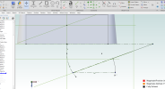
I'm trying to loft or sweep a sketch to a part face but have not had any luck.
Sweeping my sketch to a geometry target is not allowed, apparently. I also tried to loft two identical sketches with an overhead path (curved line seen in image).This particular situation is something with which I have little experience. I've swept circular sketches many times but not something like this. Have any of you done this, before? Any tips?
Thanks.
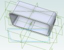
Part face curved extrusion.jpg
 

HaroldL

Alibre Super User
You cannot Loft a double sketch as you show. Create a sketch on the perimeter of the Face you want to loft to and change the angled sketch to a single profile, one that matches the face sketch. Then you can Loft BOSS those two sketches. Then create a second pair of sketches to create a Loft CUT to remove the inner part of the loft boss.

I also recorded this short video showing how to add a Sweep Boss to the part.


While I was at it I figured that I should also demo the Loft Boss and Loft Cut.

 
Last edited:

Ken226

Alibre Super User
I'm trying to loft or sweep a sketch to a part face but have not had any luck.
Sweeping my sketch to a geometry target is not allowed, apparently. I also tried to loft two identical sketches with an overhead path (curved line seen in image).This particular situation is something with which I have little experience. I've swept circular sketches many times but not something like this. Have any of you done this, before? Any tips?
Thanks.
View attachment 37474


If you don't mind uploading the file your working on, I'd like to see if I can figure out why the sweep isn't working.
 

concept

Member
Here it is. I believe that the outline sketch of the part sees interference when swept.
 

Attachments

  • Fan nozzle Insert Curved.AD_PRT
    494.5 KB · Views: 8

concept

Member
Yes. Unfortunately when I try to export that shape as an STL file, the "writing file to disk percentage number stops on 19%.
 

Ken226

Alibre Super User
I was trying to generate a sweep that kept the end face normal to the sweep path, but couldn't get in to work.

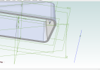
As an alternative, I created a sketch on the face of the part, same plane as your beginning sweep profile, using reference geometry to add a point at the verted, (for later addition of an axis of rotation:

1666211000495.png


Then I created a sketch on the bisecting default plane, and inserted a horizontal axis at the previously inserted point:

1666211083311.png


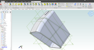
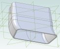
Then used a Revolve Boss to create the 3d geometry. In case this was the effect you were looking for:

1666211177129.png
 

Attachments

  • Fan nozzle Insert Curved.AD_PRT
    585 KB · Views: 3

Ken226

Alibre Super User
Yes. Unfortunately when I try to export that shape as an STL file, the "writing file to disk percentage number stops on 19%.

I tried to export your "rigid sweep" model as a .stl, and my laptop also is locked up at 19% for a minute, then crashed Alibre.

Looks like im going to have to do a hard reboot of the computer to shut it down!

Perhaps you should do a support ticket and upload that model so Alibre can look at it.
 

concept

Member
I tried to export your "rigid sweep" model as a .stl, and my laptop also is locked up at 19% for a minute, then crashed Alibre.

Looks like im going to have to do a hard reboot of the computer to shut it down!

Perhaps you should do a support ticket and upload that model so Alibre can look at it.
I did a Ctrl-Alt-Delete and shut down Alibre, only. You do not have to reboot the computer.
 

concept

Member
I'll try to do what you did as a preliminary model for 3D-printing. Then if Alibre comes up with a solution, I'll implement that as another version.
Thanks for taking the time to look at this issue, Ken.
Dave
 

HaroldL

Alibre Super User
Any tips?
I recorded my videos before you uploaded your part file so I didn't see what you had beforehand. On opening your part I can see that none of your sketches are fully constrained and/or dimensioned. That's part of the problem. What is the design intent? Where did you get the sketches from?

If you want to loft between sketches 5, 4 and 6 it will fail because you cannot loft multiple loops and sketches 5 and 4 overlap in 3D space. Also the guide curve does not start/stop on the plane of sketch 5. And it helps if the guide curve is normal the sketch planes.

If you want to sweep sketch 5 to the face of the part it will create a cusp in the sweep and fail. I suspect that's because the straight section of the path doesn't allow for the curve to transition. Also the path sketch doesn't start on the plane of the profile sketch you want to sweep nor is it normal to the sketch plane.
 

concept

Member
Sketch 5 was part of another way of doing this. I did not use it in my attempt to sweep the sketch generated by the face of the part. Yes, I am trying out different design variations, so did not think it necessary to fully define at this time. This part has to press-fit into another. Its dimensions are not very critical. The guide curve starts at sketch 6 on the face of the part.
 
Top