What's new

How to constrain two parts by sketches

manuelz

Member
In an assembly, I want to constrain a gear and a rack by using sketch lines available in each part.

My first problem is that I cannot see sketches of these parts at the assembly level.

How can I accomplish this?

Using Atom3D V26
 
Last edited:

DavidJ

Administrator
Staff member
Add suitable reference geometry to parts, then 'show reference geometry' for the parts in the assembly workspace. Constrain using the reference geometry.
 

dwc

Alibre Super User
Through the Sketch menu you can make any figure type directly as reference (I don't use the ribbon so don't know about that)
or you can make a circle, right click on that circle and select "convert to reference figures".
 

manuelz

Member
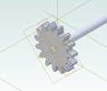
Oh, you were referring to a sketch reference geometry. Yeah I can do that, but, as I said at the beginning, I cannot see sketches of these parts at the assembly level:

1671583662109.png

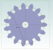
This is what I have in that gear part, when I have that sketch activated:

1671583752738.png
 

albie0803

Alibre Super User
Align them by offsetting centrelines which show up in the sketch geometry.

The sketches you want to use are only for feature creation.
 

manuelz

Member
Oh I see what you mean now.

I won't ever get a sketch circle for my constraints, but I could just use a line or a plane tangent to that desired circle, and use it to align my gear with the rack.

Thanks.
 

albie0803

Alibre Super User
Put a pitch line plane in the rack, turn on "show geometry" for the rack in the assembly, now offset the centre of the gear by half the pcd from the pitch plane of the rack.
 
Top