What's new

How to create a sketch of intersection of plane and boss

Involute

Member
Sorry for the stilted English of the subject, but I was bumping up against the length limit.

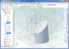
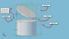
So, I extrude a boss based on a circle, creating a cylinder. The cylinder passes through an inclined plane. Is there a way for me to capture the intersection of the plane and the cylinder (an oval) as a sketch on the inclined plane?
 

wathavy4

Alibre Super User
Somewhat like this sketch?
(Part sample)

View
 

Attachments

  • 2011-09-24_121207.png
    2011-09-24_121207.png
    116.5 KB · Views: 6
  • New Part (1).AD_PRT
    238.5 KB · Views: 2

Involute

Member
That's exactly what I'm looking for, Toshi, thanks. I don't see how you get sketch 3 (the end result), however. Can you elaborate? Also, what purpose does sketch 2 serve? And, how do you delete the excess extrusion? I know, lots of questions. Sorry for being a n00b.
 

Involute

Member
HaroldL said:
Yes, if you follow the link, Max showed you the work flow here: //viewtopic.php?f=10&t=13777#p83775

Hi, Harold. I thought that was going to work for me, but, as I explained in that thread, when I translated the inclined plane back towards the cylinder, so that they were intersecting, the oval created in step 8 changed position on the plane so as to no longer be aligned with the cylinder. I've tried a number of fixes, to no avail. I've discovered, however, that I can translate the plane first, then extrude the top of the cylinder to a distance well beyond the plane. If I can then capture the intersection, I'll have the desired sketch, and it will be in the desired location with respect to the cylinder. Hope that makes sense.
 

HaroldL

Alibre Super User
Hopefully I understand what you are attempting to accomplish.
Give this a try: (Thanks to Max for pointing the way.)
  1. Create your cylinder on the ZX plane.
  2. Create Reference plane 1 offset from the ZX plane and positioned above the top of the cylinder.
  3. Create Reference plane 2 offset from XY plane and Tangent to the cylinder.
  4. Create an Axis between Ref planes 1 and 2. This is the "hinge" for the next plane.
  5. Create angled Reference plane 3 on the axis and either Ref plane 1 or 2. Angle to suite.
  6. Start a sketch on Reference plane 1; select Project to sketch and pick the edge of the cylinder.
  7. Extrude Boss To Geometry and select Reference plane 3.
  8. Start a sketch on Reference plane 3; select Project to sketch and pick the edge of the last extrude.
  9. Extrude boss the desired depth. Change the direction to be aligned with the Y-axis.
  10. Next, RMB click on the To Geometry extrude and Suppress it.
  11. Now you can adjust the offset of Reference plane 1 to position the angled, elliptical extrude.


One problem with Suppressing the Up To extrude is that the next extrude that references it will show an error (italicized text). Maybe a HIDE option would be in order. (Max, what do you think?)
 

Attachments

  • Project to sketch.jpg
    Project to sketch.jpg
    86.5 KB · Views: 10
  • lowered plane.jpg
    lowered plane.jpg
    68.2 KB · Views: 3

Involute

Member
Thanks loads, Toshi! You solved my problem. I really appreciate the effort. And in case you were wondering, this is what I wanted to end up with:
 

Attachments

  • Shelf.jpg
    Shelf.jpg
    55.5 KB · Views: 5
Top