What's new

How to create Parametrically controlled variable geometry patterns

Ex Machina

Alibre Super User
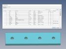
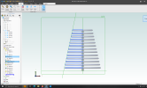
In this video I show how to create pattern where each instance is different and the variance is driven by geometry that can be selected. Any plane, face, surface, etc. can be used to drive the variable pattern. Check it out and let me know what you can do with this little method. Also, let me know if you have found other ways to make variable and adaptable patterns in Alibre.


P.S. Here are the files shown in the video so you can play with them and create your own examples.
 

Attachments

  • Variable Slot Pattern.AD_PRT
    735.5 KB · Views: 8
  • Variable Swept Pattern.AD_PRT
    482.5 KB · Views: 5
Last edited:

Ex Machina

Alibre Super User
Genius!
What you demonstrated is something that I used in SolidWorks and hoped it would become available in Alibre. Just Wow!
Actually Harold, it's more powerful than Solidworks. In Solidworks, you can either use a table driven pattern or make a value driven pattern. This, along with Joseph's surface wizardry, can actually create a pattern that follows an extruded wall, or a swept feature, or anything!!! Parametrically!!! Much more powerful than Solidworks.
 

Ex Machina

Alibre Super User
Yeah, sure Harold. It's in the Tips and Tricks section of the website. Here you go:


P.S. Actually, you've seen the thread it seems. If there is anything you don't understand about that equation and how to implement it, let me know and I'll explain it. If you have a question about it then it's highly likely somebody else will do too. Especially less experienced users. So, it's definitely worth explaining further.
 
Last edited:

DavidJ

Administrator
Staff member
The equation puzzled me until I looked more closely - it seems to be presented in a more complex than necessary way.

C1*(D1-D9-2*(d4-D9/2))/(C1^2-c1) isn't obvious, like where does the square term come from? BUT if we take the bottom line (divisor) (C1^2 - C1) and factorise, we get C1 ( C1 - 1)

Now we have C1 as a multiplier on both top and bottom of the equation, simplifying to 1

We now have (D1-D9-2*(d4-D9/2))/(C1-1) OR put another way, the distance to be filled divided by (count-1) . Count -1 is the number of spaces between instances of the pattern, so that all makes sense. It's also less to type.

[EDIT - but trying the simpler version give a dimensionality error, unless the 1 in C1-1 is replaced by a new count variable ONE (set to 1) ! Alternatively, calculate C1-1 as a separate EE entry and then use that - something like
GAPS = C1-1
then
(D1-D9-2*(d4-D9/2))/GAPS

/EDIT]
 
Last edited:

Ex Machina

Alibre Super User
The equation puzzled me until I looked more closely - it seems to be presented in a more complex than necessary way.

C1*(D1-D9-2*(d4-D9/2))/(C1^2-c1) isn't obvious, like where does the square term come from? BUT if we take the bottom line (divisor) (C1^2 - C1) and factorise, we get C1 ( C1 - 1)

Now we have C1 as a multiplier on both top and bottom of the equation, simplifying to 1

We now have (D1-D9-2*(d4-D9/2))/(C1-1) OR put another way, the distance to be filled divided by (count-1) . Count -1 is the number of spaces between instances of the pattern, so that all makes sense. It's also less to type.

[EDIT - but trying the simpler version give a dimensionality error, unless the 1 in C1-1 is replaced by a new count variable ONE (set to 1) ! Alternatively, calculate C1-1 as a separate EE entry and then use that - something like
GAPS = C1-1
then
(D1-D9-2*(d4-D9/2))/GAPS

/EDIT]
Also, the distance to be filled in the example you're analyzing is D1-2*(D4-D9/2). That is the distance to be filled with the pattern. But when doing a fill apttern you don't want the last instance to start at the end of that D1-2*(D4-D9/2) distance. You want it to end there. Hence the -D9, again in that particular example. I explain what every factor is there in the other video.
 

DavidJ

Administrator
Staff member
Konstantinos, I copied the equation directly from your variable slot pattern part.

The important conclusion was that the equation simplifies to Distance to fill/ number of gaps

The way that had been used to avoid dimensionality errors (multiplying by C1/C1) tends to disguise what the equation is actually doing, especially for those who may not be comfortable with algebra.

As with most things in Alibre, there are several ways to tackle this.
 

Ex Machina

Alibre Super User
Again, (Distance to fill - Feature length along the direction)/number of gaps.
 
Last edited:

DavidJ

Administrator
Staff member
OK 'Distance to fill' can be interpreted in more than one way.

More precise is 'distance to map first instance onto final instance'.

Was not trying to argue, just clarify for others where the (C1^2-C1) appeared from.
 

stepalibre

Alibre Super User
@Ex Machina, I am in the process of testing code and need a good test model. Your examples are great! Can use them? I will share the results.
I will convert it to code.
 

Ex Machina

Alibre Super User
You are most welcome to do so!!! Besides, everything that is uploaded here is public domain. That is what I think anyway.

I am glad you find them useful!
 

HaroldL

Alibre Super User
I know it's taken me a bit longer than I wanted to revisit this conversation. But I had some other pressing issues to take care of.

I still do not understand the equation especially the (C1^2-C1) at the end.
So I went back to what I know we used when patterning holes in SolidWorks and used that equation. The only thing is that because of the way Alibre interprets parameters I needed to do the dimensionality 2-step for one of them. After naming some of the parameters to make sense to me, I got what I think is a simpler equation, at least it makes sense to me.

Linear Pattern Equation.jpg
 

Attachments

  • EQUAL HOLE SPACING EQUATION.AD_PRT
    331 KB · Views: 0

Ex Machina

Alibre Super User
Hey Harold,

I saw your equation. And yeah, that would surely work IF both of the following conditions are true:

1) You have a feature that has a symmetry axis perpendicular to the axis of the direction. A circular hole is that type of feature. i.e. If you pattern along the X axis, you can definitely find an axis of symmetry for a circle that is perpendicular to it.

2) You measure your offset from the edge to that axis of symmetry as defined above.

In circular holes that works, but in a weird shape it might not. Or you might be able to define such an axis of symmetry but you already have a measurement from the edge of the feature (for example a square hole or boss) to the edge of the part. Then if you use your equation you will find that the spaces on either side will not be equal. In fact, the last instance is going to start at the exact point that it should be finishing at. So, at the numerator of your equation you should add the term "-Width" which appears to be the width of your feature.

The difference is that then, you will need to measure the distance from the edge, not the centre, of the feature to the edge of the part. Which is more practical for features of a shape like the curved cutout in the second part of my video.

Now, as you can see, you need to create an intermediate value to divide by so that the dimensionality checks out. That can be worked around by multiplying the entire fraction you have in your formula by "Instances/Instances". That simplifies to 1 so it does not affect the value of the fraction but, then the denominator becomes "Instances*(Instances -1)" which can be calculated to "Instances^2-Instances".

That might seem unnecessary but it solves the dimensionality issue without an intermediate parameter. And of course then you need to multiply the numerator with "Instances" as well.
 
Last edited:

HaroldL

Alibre Super User
Konstantinos,
Thanks for your feedback. As I noted we used the equation that I illustrate for patterning holes. I should have further noted that these were tapped or clearance holes punched in sheet metal. It made it easy to calculate the results needed since we had a minimum distances to the edge or in some cases a bend. We also punched, on occasion, hex holes for inserting Rivnut fasteners and square holes for clip nuts and slots used for mounting purposes. Again the equation worked for patterning them since we dimensioned to the center of the feature. EIA hole patterns sometimes were a challenge in order to get them to align properly within the cabinet.

Now, as you can see, you need to create an intermediate value to divide by so that the dimensionality checks out. That can be worked around by multiplying the entire fraction you have in your formula by "Instances/Instances". That simplifies to 1 so it does not affect the value of the fraction but, then the denominator becomes "Instances*(Instances -1)" which can be calculated to "Instances^2-Instances".
That is making a bit more sense to me, now I'll have to experiment a bit with your equation and review the results. One thing that confuses me is that you do not name the parameters but reuse the default names. I like to rename them to make them more clear as to what they are controlling.
You'll have to give me some slack on this as math wasn't my best subject and now that I'm getting a bit older the grey matter doesn't work as fast as it used to.:)
 

Ex Machina

Alibre Super User
Konstantinos,
Thanks for your feedback. As I noted we used the equation that I illustrate for patterning holes. I should have further noted that these were tapped or clearance holes punched in sheet metal. It made it easy to calculate the results needed since we had a minimum distances to the edge or in some cases a bend. We also punched, on occasion, hex holes for inserting Rivnut fasteners and square holes for clip nuts and slots used for mounting purposes. Again the equation worked for patterning them since we dimensioned to the center of the feature. EIA hole patterns sometimes were a challenge in order to get them to align properly within the cabinet.


That is making a bit more sense to me, now I'll have to experiment a bit with your equation and review the results. One thing that confuses me is that you do not name the parameters but reuse the default names. I like to rename them to make them more clear as to what they are controlling.
You'll have to give me some slack on this as math wasn't my best subject and now that I'm getting a bit older the grey matter doesn't work as fast as it used to.:)
Hey no worries! I enjoy the discussion! No problem whatsoever!

And yeah, my naming scheme is a bit minimalistic. But you can always follow what suits your style better.
 

HaroldL

Alibre Super User
Just saw this video that Too Tall Toby published and it brought to mind the one you made on variable geometry patterns.


Is that something that could be done with your equations?
 

Ex Machina

Alibre Super User
I saw that too. I will need some time to process it. My version was based on sweeps and extrusions. Funnily enough it doesn't directly work like that revolutions. I am thinking about it though.
 
Last edited:
Top