You are using an out of date browser. It may not display this or other websites correctly.
You should upgrade or use an alternative browser.
You should upgrade or use an alternative browser.
How to create Parametrically controlled variable geometry patterns
- Thread starter Ex Machina
- Start date
HaroldL
Alibre Super User
Looks promising. I tried creating two features and using a sketch pattern (as much as I don't like to use them) but even that takes a lot of work to modify each instance to get the desired results.Work In Progress

I wonder how a script could be used to create a pattern with variable feature sizes. Would be interesting to see how that could be used in variable size cutouts, like a vent or grille.
Ex Machina
Senior Member
Oh, I can get that done with a sketch. But the point is to have it Parametric. Up till now everything works parametrically (with a bit of setup) except the number of instances...Looks promising. I tried creating two features and using a sketch pattern (as much as I don't like to use them) but even that takes a lot of work to modify each instance to get the desired results.
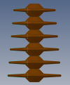
View attachment 40687
I wonder how a script could be used to create a pattern with variable feature sizes. Would be interesting to see how that could be used in variable size cutouts, like a vent or grille.
P.S. The thing is with the revolve. For the extrude my original video can be used. You just need to use a surface as the geometry to extrude instead of a simple plane. Now in the revolve, I can still get any geometry I want, and the thicknesses and spacing is parametric. But it breaks down when the number of instances is changed.
Last edited:
NateLiquidGravity
Alibre Super User
I played around with it a bit, but I didn't get a "good" solution for a revolve like array - yet. Scripting would certainly work and if you have to do something repetitive like that it's the place I'd go, but it's fun to see what else we can get the program to do.
Ex Machina
Senior Member
OK, since we have a conversation going on it, here's my file and a brief description of how I do it.
-Sketch a corner rectangle that is
-->a)As tall as the part you want to make
-->b)Slightly wider than the radius you want to end up with
-Extrude to an arbitrary depth
-Create your boundary geometry. Here's it's just a plane, but it can be a surface of any description
-Sketch the profile of your "fin" to be revolved. It is a weird one this because if you want to have a "cone" shape you need this cut to have a draft and you need to account for that
-Extrude up to that boundary
-Pattern as per my video on the top of this thread, i.e. uncheck "Pattern Geometry"
-Delete the 5 faces of the resulting solid so you're left with a surface model with the front face and the "notches" you made to it
-Sketch on that front face and project the face in
-Sketch and extrude a cylinder. This can be slightly more than the radius you want to end up with. Playing around with this can give various different geometries.
-Revolved cut the sketch and you're there.
Changing the parameters of the plane results in a correct update. Angle, position, etc. And although changing the parameters of the plane, changes the cuts, if you change the parameters of the cut or the number of instances, the sketch throws an error.
I have noticed errors in face projections in other occasions in Alibre and I try to project edges instead of faces, but how would you get around this one? Let's see if the community can get me out of this bind!
P.S. Let me note that this particular geometry can be made with a revolution and parametric cuts. But you can create a boundary that is sinusoidal, as per the video Joseph made with the Foam, and create a very elaborate revolution.
Attachments
Last edited:
