You are using an out of date browser. It may not display this or other websites correctly.
You should upgrade or use an alternative browser.
You should upgrade or use an alternative browser.
How to make a rib?
- Thread starter ask107
- Start date
HaroldL
Alibre Super User
You will likely need to set up a plane to sketch on and you need to be careful when applying ribs next to cylindrical features to make sure the rib extends to the cylindrical face.
If you are using Alibre Design here is a model you can download for an example. I use the Extrude Thin Boss for the rib on the cylinder, if you have Atom 3D that is not available.

If you are using Alibre Design here is a model you can download for an example. I use the Extrude Thin Boss for the rib on the cylinder, if you have Atom 3D that is not available.
Attachments
bigseb
Alibre Super User
Just want to point out (for the absolute noobs) that Catia's rib tool only requires you to sketch the diagonal whereas in AD you have to sketch the entire triangular shape (side profile) of the rib.Basically the same way. Select the plane you want the rib on, put a sketch on it and then extrude to either side or centrally as required.
HaroldL
Alibre Super User
But you can set up a diagonal plane and use the Extrude Thin Boss like I did on the cylinder example....in AD you have to sketch the entire triangular shape (side profile) of the rib.
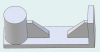
You need to be careful using the side profile when applying a rib to a cylinder and make sure to sketch inside the cylindrical surface otherwise the rib will have a gap.

By placing the sketch inside the cylinder that "problem" can be eliminated:


bigseb
Alibre Super User
Yes, I know it and I do it. I put it into the assembly as a separate part and connect it with relations. What I wanted to say is that Catia and SoliWorks' rib modeling is nothing special. At Alibre, it's also easy to do.
I agree it isn't anything special. Returning to the OPs question, yes you can use a similar method to other software and they all require some amount of input from the user.
Tip: regardless of whether you are modelling the rib directly in the part or boolean uniting it into your part, create a plane!!! This will allow you to move it about as needed without breaking your model.
DJA
Member
Maybe it is a noob question but how can we make a rib directly like in Solidworks or Catia,what will be the way for Alibre
Below is a you tube link for how to do it in Catia
More than one way to create ribs…
One technique is to create a work plane and create the rib profile on it. This involves multiple work plans (one for each rib) which can be time consuming, Also, this method does not allow for draft angle to be applied to the rib which is so critical when designing plastic parts for Injection molding. (some software, such as SW allows draft, as well as ribs to be applied later in the process. Atom3D has no such feature… do not know about ‘design’)
Another method is shown here (for Atom3D). See PDF.
It involves creating a sketch on the base/floor where the rib will be placed. Then an upward extrude for the height of the rib. Draft angle is also applied at this time. In the example I am using 3 degrees for the draft. The resulting extrusion will create a square/rectangle feature.
Next create a sketch on the face of the square/rectangular feature and do a Extrude Cut to create the corner cut of the rib. Because the sketch is on the face with the three-degree draft, It will be necessary to compensate the extrude cut, by applying a counter action using the same degree of draft to the extrude cut.
That’s all there is too it. and the proper draft angle is applied.
Attachments
HaroldL
Alibre Super User
Yes, Alibre Design does allow you to add draft to the extrude. AD also has a separate Draft option that you can apply to selected faces. One thing that you illustrate, but didn't mention in the text, is that when you apply draft to the extrude you need to compensate for it by placing the sketch inside the body of the part you are adding the rib to. Otherwise you will have a gap between the rib and the part.Also, this method does not allow for draft angle to be applied to the rib which is so critical when designing plastic parts for Injection molding. (some software, such as SW allows draft, as well as ribs to be applied later in the process. Atom3D has no such feature… do not know about ‘design’)


You can also apply a Fillet then you won't have to compensate for the draft angle of the surface. This image shows a separate Draft applied that is available in Alibre Design.do a Extrude Cut to create the corner cut of the rib.

DJA
Member

Not sure where you got the model. Look at the PDF that was attached. I think I show a .100 sketch edge INSIDE the wall to compensate for the draft. Maybe my verbal descriptions were not quite clear, but I believe the sketch was correct. I am new to alibre and have just started using Atom3D, (no draft features that I could see) so was not aware if other Alibre had draft features, so part was modeled for Atom3D.
Wish I could get Alibre Design, but out of my $$$$ range, and SS does not pay much. I had access to SolidWorks (which does has rib and draft features) when I was working, but lost the use of SW when I retired 11 years ago, so I am a little rusty. Didn't even know that Alibre existed until a couple weeks ago so thought I would give it a try. Alibre Atom3D looks a whole lot like a light weight version of SW,
Thanks for the Critique.
HaroldL
Alibre Super User
I saw the PDF but didn't notice the .100 offset to the inside. Either way it should clarify to anyone using your technique that adjustment for the draft needs to be considered or it could result in a gap at the top of the rib.I think I show a .100 sketch edge INSIDE the wall to compensate for the draft.
I just modeled it after reviewing your images.Not sure where you got the model.