What's new

How to put multiple configurations of a part, each in its own row in a BOM?

I have a subassembly which includes a part with two configurations. The only difference between subassembly configurations is in the hole pattern in that one part. The subassembly is inserted (7) times in an assembly, (4) times with one configuration and (3) times with the other. When I insert a bill of materials into a drawing, the subassembly shows up as a single Item (row), Quantity (7), with the subassembly Name in the Description column. What I want, however, is for there to be (2) Items (rows) in the BOM, with Quantity (4) in one row, Quantity (3), in the other row, and the Configuration Name in the Description column of the appropriate row. This should result in different balloon numbers for each Item. A search of the Forum didn't produce any results. Alibre Help seems to refer to different columns for different configurations in a BOM, presumably meaning multiple Quantity-by-Configuration columns in a single row, but I'm not sure that I understood. I am using Expert v25. Any help will be appreciated. Thanks. Regards, Dave
 

DavidJ

Administrator
Staff member
Just include a column in BoM has Configuration in the name. Then the different configs will be listed separately.
 
David, thanks for your input. I have worked on this since Friday and it hasn't been easy, but I have learned enough to report my findings. I reread the Alibre Help article on configurations in a BOM, and it really isn't much help. I started out by making a test assembly with two configurations, consisting of a part and a subassembly, each of which has two configurations. Both assembly configs. were inserted into a drawing. I added a config. column to my basic BOM, arranged thusly:
ITEM CONFIG. QTY. DESCRIPTION. After much work, which I will explain later, I got this to work, and saved it as a new BOM template option.

However, this is not what I was trying to do. As mentioned in my question, I want to maintain a simple traditional BOM, consisting of: ITEM QTY. DESCRIPTION, with each configuration listed with its item number, quantity, and description in its own row. Can this be done? As it turns out, yes it can: there is a work-around. Whether or not the effort is worthwhile is a matter of personal preference. What I ended up doing was to insert a column into a BOM using the Configuration property, but then naming it DESCRIPTION as the header title. Then of course you have to name each Configuration in any part or subassembly that you want to appear in the BOM with the description as you want to see it appear in the BOM. This works, and is probably not any more work than doing it some other way, since you have to enter the information somewhere anyway. Of course you can always enter BOM content manually, but if you do, it will not be parametric.

The preceding is description and explanation. What follows is complaint and criticism. If Alibre is your favorite software program, then skip this part because I am not writing this with the intention of offending anyone. I discovered four problems in my learn-by-doing exercise:

1. First, when you use the New Bill of Materials toolbar button, there is a dropdown box to allow the selection of one, and only one, configuration. When you hit Apply, it only inserts that one config., but not any additional configs. that may be in the solid model. As it turns out, you have to save the BOM, which you do when you exit the BOM editor, and then restart the New Bill of Materials dialog, and choose the next config. that is in the solid model, edit the BOM as required, and then exit and save that, apparently for each config. of the same part in the model. What's up with that? Haven't the programmers discovered check boxes (for each config.) yet? This is a tedious and somewhat error prone process. Why not just do it just one time? Or am I missing something, which I acknowledge is very possible. But there is more.

2. For some reason there are two BOM insertion toolbar buttons: the one that I just mentioned, New Bill of Materials, and Insert Bill of Materials. Not being very observant, it took me awhile to notice that there is a difference between the two dialog boxes, which are otherwise identical. At the bottom of the New Bill of Materials dialog is a radio button labeled "New Bill of Materials template". I never did try this button and don't know what it does. At the bottom of the Insert Bill of Materials dialog is a radio button labeled "Existing Bill of Materials". I finally figured out that by using the New Bill of Materials dialog twice, once for each config. in my test drawing as described above, I could assemble, edit and save a BOM, but not insert it into the drawing. Instead, to insert the BOM into the drawing required using the Insert Bill of Materials dialog with the "Existing Bill of Materials" radio button selected. Now while this worked, it is very convoluted, not at all intuitive, and quite time-consuming. It seems like the whole process should be simplified. In particular, why not combine the two dialogs into one. And where is the Help information to cover all of this? Or have I missed something?

3. The third problem that I encountered may actually be a bug. I noticed a minor error in the description names that I gave to each of the two configurations names in the one part in the assembly: I had left out a space following a comma in each config. name. I closed the drawing, opened the part, made both corrections, saved and closed the part, and reopened the drawing. One BOM line was corrected but the other was not. Reprojecting the drawing made no change. So I did what I had done every time that I couldn't get things to work: I unlinked the BOM which deletes it, closed the drawing and Alibre, deleted the BOM from the drawing folder, copied the new BOM template into the drawing folder and renamed it, reopened Alibre and the drawing, and finally went through the process of inserting a new BOM, as described above. This time both lines had been updated. Again, tedious, error-prone, and time-consuming.

4. Finally, each time I unlinked and thus deleted the BOM the Item balloons lost their registration, showing only a question mark: that is to be expected. However, after a new BOM was inserted, the Item balloons did not automatically reregister (refresh), and the question marks remained, requiring manual updating. This suggests to me that they are not parametric, and it seems to me that they should be.

Alright, I'm done: I've worn myself out trying to document my experiences. The fact that there was only one response to my initial post, and yet many views, suggests a lack of interest by Forum users in this topic, and that includes me, as well: this is not what I want to be doing. And yet I have taken the time in the hope that if my remarks are regarded as having some merit that an administrator will pass them on to the programmers. Regards, Dave
 

DavidJ

Administrator
Staff member
David,
I suggest that you raise a support ticket with Alibre. It sounds as though you have some misunderstanding of what the BoM tools should do, and also have had some difficult experiences.

1. Yes the BoM view can only show one configuration of the assembly. How could a BoM include more than one assembly config? Currently Alibre can only attach one BoM to a drawing, it would be a nice addition to be able to attach multiple BoMs to multi-sheet drawings.

2. Yes, 2 buttons; one to create BoM 'on the fly' of the assembly in current drawing, the other to insert an existing BoM file into the drawing.

3. Sorry, I really don't follow what you are describing. You have to refresh the BoM to update any changes.

4. I'm not clear why you had to unlink BoMs.

If you attach the files to a support ticket, I or a colleague will examine in detail, hopefully help you out, and identify any residual shortcomings for attention.

If you found my initial answer lacking detail, feel free to ask for more. I may have been away from office, or in middle of other tasks when I posted, so didn't add any screenshots.

I plead guilty to probably only skimming you initial post so may have only partly answered. I apologise for that.
 

HaroldL

Alibre Super User
I have a subassembly which includes a part with two configurations. The only difference between subassembly configurations is in the hole pattern in that one part. The subassembly is inserted (7) times in an assembly, (4) times with one configuration and (3) times with the other. When I insert a bill of materials into a drawing, the subassembly shows up as a single Item (row), Quantity (7), with the subassembly Name in the Description column. What I want, however, is for there to be (2) Items (rows) in the BOM, with Quantity (4) in one row, Quantity (3), in the other row, and the Configuration Name in the Description column of the appropriate row. This should result in different balloon numbers for each Item. A search of the Forum didn't produce any results. Alibre Help seems to refer to different columns for different configurations in a BOM, presumably meaning multiple Quantity-by-Configuration columns in a single row, but I'm not sure that I understood. I am using Expert v25. Any help will be appreciated. Thanks. Regards, Dave

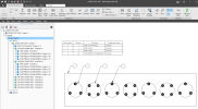
@David Watson , I set up a test model following your above description as close as as I could understand. This image is the result:

1681867720181.png


All I did was edit the BOM table to add the Configuration column as @DavidJ suggested in his first reply. As you can see, the Test Cover is an assembly with either three or four holes and corresponding fasteners. The BOM correctly calls out the number of covers for each config on their own lines.

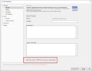
Now to add to the BOM table "confusion, IF, in the File Properties, you set the subassemblies to be treated as parts in the BOM

treat as part.jpg

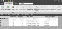
then in the BOM table you will see the only subassembly listed:

sub assy bom items.jpg

and will show on the drawing as such.

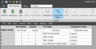
If you want all the subassembly components to be listed in the BOM table then toggle the rollup option:

bom rollup toggled.jpg

It should be noted that if you have already added balloons to the drawing before you toggle the rollup display, the balloons will no longer be associated to the new state of the table. You will need to reattach or re-balloon the drawing in that case.

As @DavidJ noted, you can only have a BOM for one configuration of the top level assembly on the drawing. It's my understanding that if you need a BOM for each top level assembly then a new drawing is needed for each config.
 
Last edited:

NateLiquidGravity

Alibre Super User
Some things I want to clear up:

I like many users saw your post and David's response and figured you got the answer you needed.

I saw you mention copying files into folders - you shouldn't copy around Alibre files in general as they contain unique identifiers that the software uses (for placing parts in assemblies and such) instead of file names. Copying the files creates duplicate files with the same identifier and can cause the software to use the wrong one.

Terminology matters: BOM = Bill Of Materials = a list of materials currently being used. It is not a design/configuration table listing all options for a design. Unfortunately Alibre Design doesn't have an option for an automatic design/configuration table yet. The closest thing I've used is make an assembly and insert one of each configuration into it to get a BOM with all the options and then hide the view of the assembly and insert a view of the part.

In the most recent version of Alibre Design you can now right click on a configuration for main views in the Drawing Explorer to switch to it.
Drawing_Project_Config.jpg
This can save a lot of time.

In my BOM I prefer to use a column for "Part-Configuration Name" and hide the original "Part Name" column.
 
Last edited:
I have a post ready to share, but I would like to include a drawing view. I haven't figured out how to do that. How is that done. Thanks. Dave
 

HaroldL

Alibre Super User
@David Watson, with the drawing open, go to File>Export. In the Export File dialog change the Save as type to JPEG, enter a name or leave the default. Select a location then select the Save button.
When you post on the forum select the Attach files button that is at the bottom left of the post window, navigate to the location you saved your image and select it. The image will be attached to the bottom of your post. If you want it to show in the post window, then select the Insert icon at the top left of the image and select to insert as a Thumbnail or Full image.

If you want to upload the actual drawing for someone to review then save the drawing as a Package file. Go to File>Package>Create. That will collect everything related to the drawing into a single file. It will likely default to save it in the same location as the drawing. Then you can attach the Package file to your post. No need to insert it into your post as it will be available for download at the bottom of your post.

If you select the Preview button at the top right you can see how the post will appear with your image attached. It will also give you a chance to proof read your post and make any changes by deselecting the Preview and going back into edit mode.
 
Last edited:
DavidJ
David, after completing a career as a mechanical engineer doing machine and equipment design, among other things, I think that I know what a bill of materials is. Further, after spending years working as a contractor for quite a few companies, I can tell you that there seems to be endless variations of bills of materials, which means that limiting the software to only supporting ANSI or ISO standards limits its flexibility and usefulness. I expect flexibility, and what I have been trying to figure out is whether Alibre can be made to do what I expect. As I explained in my second post which I am calling a report, I was able to achieve what I wanted and at this point I don't need support, and probably won't ask for it. I have given your company some valuable feedback, which I'm not sure you have recognized. Alibre is pretty good, but parts of it are not very intuitive, meaning it is a bit hard to figure out, and I am spending too much time fighting with it, compared to SolidWorks, as an example. Also, Alibre seems to lack a serious training program. I went through the entire 741 pages of the Digital Design pdf prepared for Alibre by CADArtifex, which was available sometime ago from the Alibre website. It is a very good resource intended for beginners and intermediate users. But where is the similar training material for the advanced features in Alibre Design Expert? SolidWorks has in-person training courses, each with a very nicely executed manual. I can't afford SolidWorks, and even if I could, I'm not going to pay for mandatory annual maintenance. I still like to design things and Alibre has the potential for being what I want. But it does not appear to have arrived yet. I would like to give the company an allegorical kick in the pants to get it to shape up. However, I think I may have detected a bit of a "we're programmers and we know best, take-it-or-leave-it" attitude, which I guarantee will hold the company back, if that is true. I hope that I am wrong. Now for your points:

1. You most certainly can have more than one config. in a BOM: that's what I described in my second post, achieving that result using two different methods. Also, see HaroldL's post on this topic. See the screen print, below, which shows the same results.

3. What I was describing was clear enough, I was describing the method that I used to update or refresh the drawing, which consisted of removing the BOM completely from the drawing, and starting over from scratch. How would you have refreshed the drawing?

4. I unlinked the BOM each time that I abandoned one preparatory to inserting a new BOM from scratch to make sure that there was no remaining connection to the BOM that the drawing might be expecting. Whether I "had to" I don't know. Keep in mind that I have described what I did, not knowing for sure what I should be doing.

Alright, thank you for your feedback, I appreciate your help.

HaroldL
Harold, you did exactly what I had already done, as described in my second post. However, I used a different assembly than the one described in my first post, and the configuration column was in a different place than yours. However, as I explained in both my first and second posts, this was not what I wanted. What I wanted was a BOM with ITEM QTY. DESCRIPTION in the header, and not a fourth column taking up space. The first part of my second post describes how I finally achieved the desired result, not, however, without a lot of grief.

You say "As @DavidJ noted, you can only have a BOM for one configuration of the top level assembly on the drawing."

Maybe we are talking past one-another, but aren't you showing a top level BOM with two configurations in your first BOM example. See the screen print, below, which shows the same results. Thanks for your input, effort, and help.

NateLiqGrav
Nate, I am very surprised by what you are saying about copying files. Is this only in Alibre, or is it in all Windows-based software in general? Does the Save As command have the same problem? So if I have BOM in my drawing (project) file and want to replace it, and so I delete it, and then want to insert a BOM template file from a different folder, and then rename it to the same name as the deleted BOM, how would I do that without copying? What I have been doing is to copy the BOM template file into my project file and then renaming it to same name as the deleted BOM. I could also open the BOM template in the template folder, use Save As to rename it, and then cut and paste it to my project folder. But in both cases a copy operation is involved. Or I could open the BOM template in the template folder and do a Save As directly into the project folder using the new name. How would you do it?

I don't know why or how I would use a configuration list. Thank you for your input, I appreciate your help.

I started out years ago with AutoCAD, then started out to move to 3D CAD by getting some Pro E training, then SolidWorks, and AutoDesk Inventor, both of which I have used for hire. More recently I have been learning Alibre. In each of these3D programs, I think that it is accurate to infer that the solid modeling development has taken precedence over the 2D portion of the programs, the solid modeling being more glamorous and impressive than the more boring 2D drawing. Yet in probably almost every case the solid models are not the final product, but rather a set of 2D drawings, which suggests to me that the software development of the 2D portion of any 3D solid modeling program is at least as important as the 3D development.

So to summarize, I first suggest for consideration that Alibre could benefit from a review to determine where various parts of the program might be simplified and made more intuitive. Second, the 2D portion of the program needs work, especially regarding completeness, and ease of use. The computer is a wonderful modern tool that is ideal for rapidly doing repetitive chores, and any CAD program, when programmed with that principal in mind will certainly benefit, but don't make users do what the computer can do. And finally, Alibre seems to be deficient in training materials. I believe that noticeable improvement in these areas will considerably improve Alibre's competitive position in the CAD market, as well as its value to existing customers. And don't forget or neglect your customers as a source of help: every user can be turned into a product tester providing valuable evaluation and feedback, and every user can become the source of innovative ideas and input. Make maximum use of the help of your customers every day, all year around.

Best regards, Dave

In the BOM below, the Description column is actually the Configuration property with the column header renamed DESCRIPTION. Notice that there are two configurations in a top level assembly drawing. Items 1 & 2 are the No Hole configurations of a part and a subassembly, and Items 3 & 4 are the 1" Hole configurations of the same part and subassembly. Items 1 & 3 are the No Hole & 1" Hole configurations of the part. Items 2 & 4 are the No Hole & 1" Hole configurations of the subassembly. I hope that you can read the BOM. And don't ask what the assembly is because it isn't anything but an illustration.


BOM Test Assembly.jpg
 

DavidJ

Administrator
Staff member
David,

I apologise if my comments felt like I was being patronising in any way, any comments relating to BoM were specific to Alibre's BoM tools.

Your descriptions of what you are attempting are somewhat unclear to me - but that's not surprising, I often find that what is obvious to the person who has been working on it is not at all clear when presented mainly in text to others. I'm sure my own pre-conceptions and experience also play a role.

I can see that your BoM includes different configurations of sub-assembly, however the BoM itself will only relate to one config of the top level assembly. I'm guessing you've essentially added an extra assembly level as a workaround - which seems a sensible way to reach your goal.

I am certainly not a programmer (I've dabbled a bit with coding over the years is from PLCs to Mainframes, but only at a basic level) - my role within Alibre is to assist users, and also to clarify and capture enhancement requests. I began doing some work for Alibre only after several years as an end user in my own business, and doing customer support work for an Alibre reseller.

Alibre is interested in receiving feedback from those using the software - our support tickets are probably the best way to submit your feedback or requests as this gives the opportunity for clarification, or to let you know that a particular item has already been requested, or is even already planned. Wherever possible, support will try to suggest some method or workaround to achieve your aim or a reasonable alternative using the current toolset.

I can't guarantee that all feedback will be adopted, but I can assure you it is all reviewed.

I'm particularly intrigued by your comment mentioning 'limiting the software to only supporting ANSI or ISO standards', these 2 families of standards cover most of the world (though note that we also include JIS drawing templates). Are there other standards which you feel should be added, or do you feel that following ANSI & ISO standards restricts some particular thing or things that you want to use the software to do? I'm happy to continue the discussion here if you wish, or to process a support ticket on this subject - https://support.alibre.com/s/

I must apologise for an error on my part, not being in front of my computer at the time, I responded without checking about BoM buttons in the 2D workspace. I responded incorrectly - the 2 functions I mentioned ARE accessed via a common dialogue from ONE button. The other button is to link or re-link an existing BoM to a drawing (for example if the files have been moved and hence lost connection).

Regarding not copying files externally - this Help section may explain why this is important
 
David, thank you very much for your response, which I am still trying to digest. I was trying to expand the drawing that I inserted above, but managed to destroy it. I remade it in a slightly more complicated way, and discovered when I inserted the BOM that a flaw was revealed in my method, which did not appear in the first asssembly. I will probably post a sceen shot of that after I finish working on it, and also answer your question on BOM standards. I do suspect that some of the trouble that I had initially was because I copied files as you and NateLiqGrav warned me not to do. Dave
 
Top