What's new

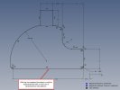
I can't see how to arrive at a fully defined design.

pridbor

Senior Member
What am I missing in order to get my design fully defined?

I often get frustrated when creating measurements for a design, and I get all my lines "orange", and in my current case, even one black, but I still can't figure out which measurement I'm missing to get them all black.

It doesn't really matter, nor is it urgent, for this design.

But I should like to learn what I'm overlooking.

Thanks in advance

Preben
 

Attachments

  • PCB Outline for Cx Oil.AD_PRT
    370 KB · Views: 7

schenman

Member
What am I missing in order to get my design fully defined?

I often get frustrated when creating measurements for a design, and I get all my lines "orange", and in my current case, even one black, but I still can't figure out which measurement I'm missing to get them all black.

It doesn't really matter, nor is it urgent, for this design.

But I should like to learn what I'm overlooking.

Thanks in advance

Preben
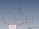
I projected the face of the feature to the sketch and deleted the original sketch and defined the projected sketch. It is now fully defined. The original has lots of points on it that I couldn't delete.
A copy of the design is attached.
Regards
 

Attachments

  • PCB Outline for Cx Oil Copy.AD_PRT
    357.5 KB · Views: 3

HaroldL

Alibre Super User
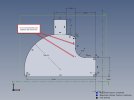
After checking over your sketch I added the missing Tangent constraints. and reduced the amount of dimensions needed to define it. I found two points at the bottom corners of the sketch that were related to the bottom horizontal line that were not constrained and could be moved by dragging them. I deleted and replaced the line and the points were deleted along with it. I then was able to apply a few dimensions to fully define the sketch.

I've seen this before a few times where a point related to an entity is created and it is not constrained to anything which makes the sketch not fully defined. It takes some time to examine the sketch for 'floating' points and either constrain them or delete and replace the entity they are related to.

SKETCH NOT FULLY DEFINED.jpg

FULLY DEFINED SKETCH.jpg
 

Attachments

  • PCB Outline for Cx Oil - fully defined sketch.AD_PRT
    378.5 KB · Views: 2

Ex Machina

Senior Member
Generally speaking, you must try to use as few dimensions as possible. That "rule of thumb" will help you start to get a feel of how you should be defining your sketches. Also, read up on "Design Intent" in Parametric CAD software. It's a concept only applied to them, not AutoCAD, SketchUp, and the like. But once you get the hang of it, you can make Parametric Magic.

Finally, you have really good advice on this thread. Especially, Nate (the universal "click-and-drag" method) and Harold (reduce dimensions, increase constraints). I also have a video on my YouTube channel that you might find interesting on Design Intent.

 
Last edited:

pridbor

Senior Member
I did go through all of the suggestions above and have learned a lot.

I started a new version of my design for each post and did as proposed.

Virtually all went well, but for Harold's approach, where there's one element that I have trouble with.
I liked the minimum number of measurements required using the constraints in a better way than I have done in the past.

Thanks all

Preben
 

Attachments

  • PCB Outline for Cx Oil Min Measurements.AD_PRT
    361.5 KB · Views: 2

HaroldL

Alibre Super User
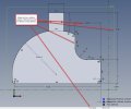
Looking at the sketch it appears that Alibre created a point at the intersection of the vertical and horizontal lines. Likely when the the fillet was applied.
I could click and drag the point so I deleted and replaced the line.

loose point.jpg

replaced line.jpg

Repeat these steps on your model and it should fully constrain the sketch.
 

DavidJ

Administrator
Staff member
In my opinion that sketch is starting to get a bit complex. I would probably break it down into 2 or even 3 sketches, and maybe use 3D fillets in place of some of the 2D fillets. It all helps to keep sketches simple and hence easier to edit.

There are usually multiple ways to reach the same result.
 
Last edited:

pridbor

Senior Member
I stared myself blind looking for that "extra" point, never saw it :)

And yes, simpler is always better, although when I started on this I felt that it was a simple design, but a good suggestion.

I never thought about this as a 3D design as I just needed a 2D drawing for the outline of a PCB I'm designing.
I will try your 3D fillet idea just to remember it for another time.


Thanks again all, it has been very informative to me!

Preben
 
Top