What's new

I wish Alibre had an easier way to dimension a 2D drawing, maybe as easy as the method used in Shaper3D.

Don't get me wrong, I prefer Alibre for most of the design aspect of creating parts, assemblies, setting constraints, and how 2D dimensions look, ... BUT I find selecting features and placing their dimensions sooooooooooooooo onerous in Alibre. I much prefer the dimensioning method in Shaper3D. That said, the options of how dimensions are displayed in a Shaper3D -> 2D drawing are limited. Could you please come up with a better dimensioning process?
Kind regards
 

dwc

Alibre Super User
What is it that is "sooooooooooooooo" cool in Shaper3D dimensioning ?
Less work than selecting features to be dimensioned is hard to imagine.
I find that so called "automatic" dimensioning usually doesn't do what I want and I spend more time correcting than if I simply placed the dimensions to start with.
And then there is always the one "automatic" dimension that I forgot to correct :(
Hi dwe
I’m not sure i understand your response. All of the words seem to be in English, but your question seems to be gibberish. Kind regards
 

HaroldL

Alibre Super User
I take it that you are not watching the new videos on the Alibre YouTube channel.


Let me add that using design dimensions in a drawing is something that I have never used in all my 25+ years as a CAD designer/dafter using various systems including SolidWorks and Alibre. I prefer the manual method selecting those items and features on the drawing that need to be dimensioned for clarity of design and manufacture.
 
Last edited:

DavidJ

Administrator
Staff member
The Shaper3D web site has almost nothing on 2D drawing dimensioning - the little they have looks very similar to Alibre.

You'll have to explain exactly what it is that you find onerous, and how it's better in Shaper 3D. Before anyone considers changing anything, they first need to understand what it is you are asking for, or at least what you find problematic....


[EDIT - I found another video about 2D drawing dimensions in Shaper 3D
. If anything it looks more complex to me than Alibre, as you have to select dimension type before placing the dimension - Alibre works out what type is needed based on your selection. Will be interested to hear what aspects of it you prefer.....]
 
Last edited:
Ich spreche Englisch, Französisch und auch ein bisschen Deutsch. Sie können wählen. Oder ist in diesem Zusammenhang "wählen" besser als "entscheiden"? Danke und bis spatter.
Ich werde versuchen, meinen Kommentar/meine Frage genauer zu formulieren.

Ich habe Tutorial 1 im Alibre+Design_Book_Digital abgeschlossen. Das Tutorial beginnt auf Blatt 719 des Handbuchs.

Ich habe mich genau an die Anleitung gehalten. Nachdem mein erster Versuch nicht zu den gewünschten Ergebnissen führte, habe ich es noch einmal von Anfang an versucht und bin dabei den Anweisungen gefolgt. Hier sind einige der Probleme, die ich beim Bemaßen der Zeichnung habe:

• Ich kann „Abschnitt A-A“ überhaupt nicht bemaßen. Ich kann den Kreis nicht auswählen, um ihm eine Dimension zuzuweisen.
• In der Vorderansicht kann ich kein Maß von „3,0“ oder „2,0“ Zoll zwischen der Grundplatte und der Mitte des Lochs einfügen.
• Alle anzuzeigenden Dimensionen Stehen in Klammern.

Ich habe ein Teil in Shaper3D modelliert und hatte keine Probleme beim Einfügen der Abmessungen. Wenn ich jedoch Bemaßungen richtig einfügen kann, bevorzuge ich die Optionen, die Alibre für die Bemaßungsstile bietet, deutlich.

Vielen danke dwc, Duolingo und Google Tranlate!
 

DavidJ

Administrator
Staff member
If having problems selecting figure to dimension, the first thing to do is make sure that the driver for your graphics adapter is up to date.

I've see lost of people struggle to select figures because of either having Window default drivers still in place, or having a very poor early driver.

That e-book isn't the best at describing how to dimension...
Thanks for that! I will definitively check my graphics adapter tomorrow. That was a helpful suggestion.
 

DavidJ

Administrator
Staff member
Eric - I think that you may be using a DisplayLink device (could be a DisplayLink screen, or connection via a docking station) - do you have the same difficulty if not using DisplayLink.
 

NateLiquidGravity

Alibre Super User
I think this thread is getting farther away from the problem.

Translated by google:
Here are some of the problems I have when dimensioning the drawing:

• I cannot dimension “Section A-A” at all. I can't select the circle to assign a dimension to it.
• In the front view, I cannot add a “3.0” or “2.0” inch measurement between the base plate and the center of the hole.
• All dimensions to be displayed are in parentheses.
It sounds like you are using Design Dimensions. They show dimensions used in the creation of the part model through to the drawing. Typically you should not do that as often the way a part was made in 3d is not the way the part will be made in real life. Only Design Dimensions have the advantage of being able to edit the part size from the drawing - not all dimensions added to the drawing can do that.
 

DavidJ

Administrator
Staff member
Nate, the tutorial referred to in the e-book is all about creating a 2D drawing from part and adding dimensions - no use of design dimensions.
 

NateLiquidGravity

Alibre Super User
Only the original poster knows whether they checked the box for "Design Dimensions" when they inserted the view or right clicked the view and selected "Reproject Design Dimensions".
 

HaroldL

Alibre Super User
• Ich kann „Abschnitt A-A“ überhaupt nicht bemaßen. Ich kann den Kreis nicht auswählen, um ihm eine Dimension zuzuweisen.
• In der Vorderansicht kann ich kein Maß von „3,0“ oder „2,0“ Zoll zwischen der Grundplatte und der Mitte des Lochs einfügen.
• Alle anzuzeigenden Dimensionen Stehen in Klammern.
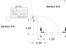
I can confirm that Section A-A cannot be dimensioned. I just went thru the tutorial to create the part and then the drawing. After creating Section A-A I cannot select the geometry in the view to apply the dimension. I made sure to move the view so it is not inside the front view boundary as that can sometimes affect selecting items in a view. I even moved the location of the cutting plane line but that didn't help either

I was able to apply all other dimensions called for in the tutorial.

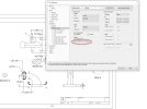
As for the dimensions all having parentheses, go to the Dimension Styles in File Properties and check if by chance you have "As Reference Dimension" selected. Deselect it and click Apply if you do.

dim set as ref.jpg
 
Last edited:

DavidJ

Administrator
Staff member
I had no problem dimensioning section A-A, section B-B was a little tricky until the nodes highlighted on the ellipse.

Harold, was your section A-A across the parallel section of the loft?
 
Last edited:

HaroldL

Alibre Super User
Harold, was your section A-A across the parallel section of the loft?

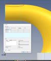
At 1.25" it's .25" inside the straight section.

1702283485865.png

1702283677096.png


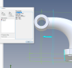
The loft doesn't appear straight between the two circle sketches. That may be the issue. :confused:

bad loft.jpg
 
Last edited:
I can confirm that Section A-A cannot be dimensioned. I just went thru the tutorial to create the part and then the drawing. After creating Section A-A I cannot select the geometry in the view to apply the dimension. I made sure to move the view so it is not inside the front view boundary as that can sometimes affect selecting items in a view. I even moved the location of the cutting plane line but that didn't help either

I was able to apply all other dimensions called for in the tutorial.

As for the dimensions all having parentheses, go to the Dimension Styles in File Properties and check if by chance you have "As Reference Dimension" selected. Deselect it and click Apply if you do.

View attachment 40321
 
I turned off the "As Unit Dimensions" in the "File Properties -> Dimension Styles -> Units and Tolerances" and that take care of all the parentheses issue. Thank you very much.

I checked my display drivers and they all seem to be up to date.

I noticed in DavidJ's 3:33 AM post that in his screen capture, there appear to be orange(?) dots or nodes appearing in his A-A section view and towards the front of the base plate. Theses nodes don't appear in my drawing. Could this be the issue? Do I need to see these nodes to insert the "2.0" and "3.0" inch dimensions from the front face to the base to the A-A section view and to the center of the hole?
 
Top