What's new

Interaction in an assembly

jcdammeyer

Senior Member
I've been modeling this project drawing the AD_PRT files from either the 2D drawings or in some cases Fusion360 converted STL to STP or GeomagicCAD STL to AD_PRT.
I can move the arm up and down independently. However, when I rotate the base the arm also moves up and down. It's quite possible that some of the techniques I use to fasten the various parts together causes this interaction but I'm not sure how. Perhaps someone with more experience in assemblies can tell me where I'm going wrong.

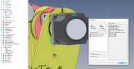
Here's screen shot of what the current progress looks like. I've included the entire assembly as a PKG. The motors and planetary gearboxes aren't perfect but close enough I think. Nor have I placed any screws or bolts but just used coincident to line things up. The ball bearings are imported STEP models converted to parts or assemblies.
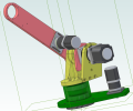
1676941822136.png
 

Attachments

  • AR3_Base.AD_PKG
    3.6 MB · Views: 3

HaroldL

Alibre Super User
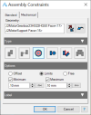
Turning OFF Minimum Motion allows the base to be rotated without the arm moving up and down.

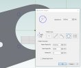
As a side note: If you change the bolt hole diameter on the J2 Motor Support
1676949438854.png

to match the spacing on the motor gearbox
1676949475644.png
you should be able to reapply the Coaxial constraint.
 

jcdammeyer

Senior Member
Turning OFF Minimum Motion allows the base to be rotated without the arm moving up and down.

As a side note: If you change the bolt hole diameter on the J2 Motor Support


to match the spacing on the motor gearbox

you should be able to reapply the Coaxial constraint.
Awesome. That minimum motion was killing me with frustration.

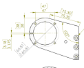
Yes. I see what you mean. The original drawing has:

Which is how I made it. I hadn't examined why there was an issue. Thanks for pointing that out. It's possible the designer made it a bit bigger so that as the clamp is compressed the holes do end up closer together.
1676955720087.png
1676954762601.png

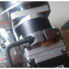
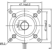
The StepperOnline Motor is shown below and who knows how accurate the barrel of the reduction gear is or how much the clamp moves. Haven't ordered the motors yet. You can see in the above photo how they prevent the motor from touching the movable arm.
1676955277439.png

Plus with alignment issues it's also possible that the holes need to be made larger so the shaft of the motor is precisely in line with the arm spindle.
 

jcdammeyer

Senior Member
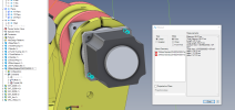
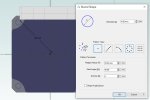
Making the changes has resulted in an interesting issue.

MotorPlate-Holes.jpg
Motor-Holes.jpg

The only way I can get rid of the error on the coaxial constant is to set coaxial limits to +/- 0.1mm. I was very careful to edit each of the parts to ensure the dimensions were exactly the same. Yet they wouldn't line up until I added the tolerance..
1676968288425.png
The first time one set of holes had been made as a rectangular pattern and the other as a circular. There was a teensy difference in the calculations that didn't show up as 47.15 but instead of 47.147052mm But in the above dialog only two decimal places show even if more are entered. Once I changed both to a circular pattern I expected the 4 and 4.5mm holes to be coaxial. But they weren't. Very odd.
Maybe a left over measurement from the previous rectangular somewhere else.

Anyway, Making progress. Another joint has been completed. This time the problem was the 2D CAD drawings for two parts had holes on a different radius.

Thanks again for your help.
 
Top