What's new

Internal gears now available!!

albie0803

Alibre Super User
Just installed v 1.3.0.0 at home on V26 professional and have found issues:
Module values above 1.0641 cause NaN in several fields
More than 20 Teeth cause the same thing

NaN results happen at different input values:
1M 0HA 18T,18T PA can get down to 0.1
1M 0HA 18T,19T PA can get down to 13.4
1M 0HA 19T,19T PA can get down to 18.7
1M 0HA 20T,19T PA can get down to 22.7

1687607299585.png
 

bolsover

Senior Member
Hi @albie0803
Thanks for the feedback. I'll check these values when I get home from holiday.. In the meantime, I'm not sure why you would want a pa of 0.1? I should probably prevent anything less than 14.5 degrees. Also, worthwhile setting the operating centre distance to match the calculated as a starting point whenever you change the tooth count. I had to decide which way the calculations worked - either allow centre distance adjustments or make this a fixed calculation and make profile shift adjustments very very difficult.
David
 

NateLiquidGravity

Alibre Super User
I don't know squat about gear calculations but from UI perspective - perhaps a lock/unlock button next inputs with a tooltip explaining what the lock does.
 

bolsover

Senior Member
Hi @NateLiqGrav Hmmm, lock/unlock is certainly possible... maybe, I'll do some tests. I have been working on some possible changes to the UI - I always intended to make the calculations much clearer but had issues with the presentation of the formulae. I have however been experimenting with the use of Latex. Latex is a 'custom language' aimed squarely at this type of maths. My current aim is to separate the calculated fields from the user input fields. It's my guess that the majority of users don't care about the calculations and just want to create reasonably accurate gears with minimal input. There is a fine balance - very simple inputs - say just for a single gear - and accept that the output lacks refinement. Or have a more complex set of inputs (for a gear pair) that allow for the generation of functional gears.
I'll be the first to admit that some of the maths is complex!
David
 

albie0803

Alibre Super User
I'm not sure why you would want a pa of 0.1?
It was more the point that different values caused NaN errors

The first action of changing the module value to 4 causes NaN errors straight away.

OK, adjusting the operating centre distance removed the NaN errors

Suggestion:
Have the Operating Centre Distance auto match the Standard Centre Distance when input changes are made so that NaN errors don't happen.
Logically working down the page, the Operating Centre Distance can then be adjusted as desired.

Your Profile Shift or OD adjustment by addendum co-efficient ratio doesn't work if the centre distance doesn't change.
What if I want a standard centre distance but want the 97t bull gear to be undersize and the 27t pinion to be oversize? This is a common scenario.
As the pinion is turning almost 4 times the speed of the bull gear, a common design feature is to oversize the pinion so that the teeth are fatter, giving a longer wear life to the pinion.
The bull gear is then reduced by the same amount to keep the centre distance standard.
 
Last edited:

bolsover

Senior Member
Hi @albie0803
The NaN are an indication that the calculation has exceeded the limit of double (32 bit) number precision. I suppose I could flag this in some way but it's tricky with so many calculations.
I agree an 'auto match' would be ideal - I have tried to implement - but so far without success. Maybe I can add an auto/manual button with the default auto.
I confess I hadn't considered the issue of an oversize/undersize pair with standard centres - certainly needs doing!
I'll take a look at these issues when I get home from holiday.
Many thanks for the feedback - essential to improvement.
David
 

NateLiquidGravity

Alibre Super User
I sometimes do validation checks of user input. I change the background color of an input to light red if that input will result in an error. I also start with a disabled "create" button and only enable it if all inputs are valid. There is more to it like resetting things, but it all depends on your needs. I do also run a full check in the button click to ensue nothing was sneaking through.
Some will say you must do this in the validating events for each input, but sometimes I just use a timer to run the check - depending on the amount of processing it takes.
 

bolsover

Senior Member
@NateLiqGrav
No doubt there is more I can do by way of validation. There are not actually too many inputs. There are no real limits on module size except it must be >0. Pressure angle - TBH I'm not sure what limits should apply. Common values are 14.5, 20 and 25 but I guess there may be some 'special' cases. Maybe I should limit to values between 10 and 30?
Helix angle - again, I'm not sure what hard limits should apply - perhaps limit 0-45?
Tooth count - at present, the routines can work with values above about 17. There is no real upper limit but (from memory) I think I set this at 1000. (I seriously doubt Alibre performance would allow anything much higher anyway). The lower limit is because I have not implemented any undercutting routines - seriously difficult.
Other variables apart from centre distance have more minor impact on the geometry. Calculating 'standard' centre distance is easy but there are many use cases where this needs to be adjusted - and finding the limits of that adjustment is somewhat emperical and thus difficult to validate. The clearest indicator that something is wrong is when the contact ratio is < 1.2 but even this is not a hard rule.
Clearly more work needed but it will have to wait a little longer - sunning myself in Greece takes priority.
One thing I've already started on is to make the calculation formulae more obvious. There is a nice C# library called Latex that allows for generation of some really nicely formatted visuals.
I also aim to add some help.
David
 

GIOV

Alibre Super User
Hi David,
I am running your utilities for Alibre Design in V21:
I need the following parts in AD21 that are in the folder Gear:

HelicalPinionTemplate
HelicalWheelTemplate
PinionTemplate
WheelTemplate

Thanks in advance,
GIOV
 

bolsover

Senior Member
Hi David,
I am running your utilities for Alibre Design in V21:
I need the following parts in AD21 that are in the folder Gear:

HelicalPinionTemplate
HelicalWheelTemplate
PinionTemplate
WheelTemplate

Thanks in advance,
GIOV
Sorry I should have mentioned in my earlier reply..
The files you mention are in the Github source code repository here Template Files.
The files WheelTemplate and PinionTemplate are identical apart from name.
The Files HelicalWheelTemplate and HelicalPinionTemplate are identical apart from name.
If you are building the code from source, you could probably recreate thse files using V21..
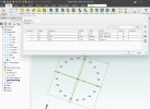
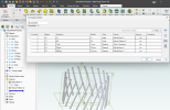
Here are screengrabs of the Wheel files.
Important that the sketches are named as in these images and that the parameter names are identical - these are used in the gear generator routines.
For example the C1 feature pattern count in both these files is 20 - this is replaced by the tooth count of the actual gears and the sketch 'Tooth' has the single circle feature deleted and then replaced with a more complex sketch of the actual tooth profile.

WheelTemplate.png

HelicalWheelTemplate.png

David
 

bolsover

Senior Member
@GIOV
Hi GIOV. The .stp files are attached.
David
 

Attachments

  • HelicalWheelTemplate.stp
    116.2 KB · Views: 2
  • WheelTemplate.stp
    44 KB · Views: 1

GIOV

Alibre Super User
David.
HelicalPinionTemplate Identical Ok
HelicalWheelTemplate STEP Ok
PinionTemplate Identical Ok
WheelTemplate STEP Ok

The files WheelTemplate and PinionTemplate are identical apart from name.
The Files HelicalWheelTemplate and HelicalPinionTemplate are identical apart from name.
I'm going to see how I figure this out.
Thanks
GIOV
 

bolsover

Senior Member
I'm going to see how I figure this out.
Thanks
GIOV
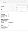
Best of luck! - As it happens, I'm working (very slowly) on some updates.. The first thing I want to do is implement a much simpler and cleaner interface for 'standard' gears:
Screenshot 2023-07-12 173110.png
The idea is that the user should be able to generate 'standard, spur and helical gears with the minimum of input parameters. So parameters such as profile shift/centre distance adjustment, etc. will be set to standard default values.
I will keep something like the existing tool for the 'expert' user who wants greater control over more parameters.
There will be no need to change the template files since nearly all the background calculation will remain the same.

There is the prospect that the Alibre API wil be updated in future and allow for circular pattern features - IF this happens, then I can get rid of the template files altogether.
David
 

albie0803

Alibre Super User
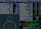
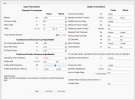
Here is a screen shot from the Gear program we have at work. You can see the type of input and output info it uses. It doesn't have gear thickness or hand as it only outputs dxf files. There is actually a sub screen which will recommend the gear thickness depending on the amount of torque being transmitted.

1689628864523.png
 

bolsover

Senior Member
@albie0803
Thanks for the screen grab - great infomation - very helpful - here isa screen grab of what my 'new' simple routine would give for the 25 tooth gear:
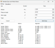
Screenshot 2023-07-18 123636.png
I've also attached the generated Alibre part file.

I also checked the output of my original gear generator against the data from your screen grab. All the major items are in agreement - even the contact ratio.
Where your program wins out is in the detail of the tooth profile data and the measurement infromation.
I'm interested to know more about the Addendum modification and recess-approach graphs - what do these graphs do? I'm guessing the Addendum modification graph indicates when undercutting of pinion (xpUc) and gear (xgUc) will occur - but what are xpPt and xgPt?

Can I ask a favour? Could you provide a screen grab for the following inputs:
Module 3
Pinion 12 teeth, Gear 24 teeth
Pressure angle 20
Addendum modification Pinion 0.6
Addendum modification Gear 0.36
Operating centre distance 56.4999

The above is one of the 'standards' against which I check my calculations; it would be very helpful to have some additional confirmation that I'm on the right track.

Also, does your program work for helical gears?
If so, could you check for the following values:
Normal Module 3
Normal Pressure angle 20
Helix angle 30
Pinion 12 teeth (L), Gear 60 teeth (R)
Addendum modification Pinion 0.09809
Addendum modification Gear 0.0
Operating centre distance 125.0
I'm not sure your program uses this: Centre distance increment factor 0.9744

Again, this is one of the standards I've been using - so confirmation of the calculations would be most welcome.
Thanks..
David
 

Attachments

  • M2.5A20B0Z25.AD_PRT
    1.5 MB · Views: 5

bolsover

Senior Member
Screenshots as requested
Many thanks. Happy to report that my calculations agree - phew!
I was thrown for a moment by the Transverse Pressure angle until I realised that your calculator shows values in Degrees, Minutes and Seconds whereas I'm using all decimal values.
I like the use of a graph to illustrate the limits before undercutting occurs - I might explore that.
I still need to get my head round the undercutting profile though - I know it should be a trochoidal curve but I'm as yet unsure how to determine the point at which this intersects the involute of the tooth. I have a suspicion it might be necessary to use an iterative process untill a 'good enough' fit is achieved.

Thanks again - now back to checking out the new V27 features...
David
 
Top