What's new

Is there a mechanical constraint in Assembly to make stilsons move as they should?

Stu3d

Senior Member
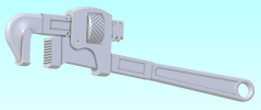
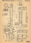
I have been modelling the stilsons on page 172 (page190 of the pdf) in the T. Carreras Soto drawing collection.
It is still a work in progress but I have put the parts in an assembly to see how it fits together and tweak a few dimensions.
Is there a way to make the jaws (part 2) move by turning the knurled wheel? At the moment I have just applied two constraints so they are in the centre of the wheel and lined up with the fixed jaws.

Soto stilsons.pngCarreras Soto stilsons page 172.png
 

Attachments

  • Soto stilsons.AD_PKG
    1.5 MB · Views: 6

Ken226

Alibre Super User
I was wrong on the rack/pinion constraint. I edited my post to reflect.

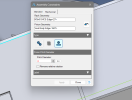
Use the screw constraint.
 

Attachments

  • 1711986371913.png
    1711986371913.png
    65.3 KB · Views: 12
Last edited:

Stu3d

Senior Member
Thanks everyone. When I originally looked at the mechanical constraints I assumed the one in the middle was a worm gear :rolleyes:
Now to go and try and make the curves on the jaws (part 2) more accurate which I am finding very difficult due to many curves.
 

HaroldL

Alibre Super User
That wrench looks pretty good.
I've worked thru all the Soto books and have done most of the exercises in each one. This is one I haven't taken a shot at yet but will soon. There are drawings some that are missing information or that you really need to scour the drawing for dimensions.

Lately I've been following some of the Inventor, SolidWorks, and Catia video tutorials on YouTube just to see if they could be done with Alibre. Except for some of the 'special' tools the other programs have Alibre can handle them, just with a different workflow.
 
Top