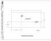
This drawing is an example of how we construct our Parts. Since most woodworking parts are rectangular in nature, we begin with a sketch of a rectangle on the XY Plane.
We define the X and Y dimensions of the Part, and then the X and Y Offset to the Left and Bottom respectively. Then Extrude Boss the Sketch via the MidPlane option.
This becomes the basis for all Configurations in a multi-part Part file, as well as individual Part files. It has proven to be the most efficient construction method for us, and the Offsets can be used to locate the part relative to the origin. This allows parts to be constrained about the origin and reference geometry, and shift their location based on equations in the part files, rather than requiring changes to the constraints in the Assembly. Our assemblies contain only zero offset Mate constraints to locate parts relative to their part Z coordinate (except for the location of a Vertical Divider).
I hope this template eases the transition to using Alibre Design for your woodworking modeling.