What's new

Locking a hub in an assembly.

jcdammeyer

Senior Member
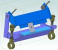
I've been modeling my 12" box pan brake with some improvements. Ultimately I'll want to change from the eccentric fore/aft adjustment to something linear. That's because the fore/aft also raises and lowers the bending fingers. I don't like adjustments with side effects.

With the simulation I can move the fore/aft levers and the fingers move in and out and up and down. However once locked (set screw holes by the eccentric hubs) on the real machine then moving the two large push rods lifts the fingers up and down around the pins in the outer arms.

The question is, in the assembly, is there an easy or simple way to prevent the part of the hub with the levers from turning in the frame so that when the entire frame is moved it now pivots on the pins in the outer frame?

I've included the pkg file if this will help.

Oh and I can do it this way. But it's tedious.
1672808632642.png
 

Attachments

  • BoxtPanBrake.AD_PKG
    2.9 MB · Views: 4
  • PartialAssembly.jpg
    PartialAssembly.jpg
    488.6 KB · Views: 23
Last edited:

jcdammeyer

Senior Member
John, here's a short video of a solution that I worked up for your brake.


And here is the STEP file of the assembly for you to analyze.
Oh I like that solution. Very clever.

I've got my simulation working to the point where I can move things and measure. This screen shot shows the other issue which is the design, unlike more expensive brakes uses a single point contact to hold down the material. It was only after I was using the brake that I realized that the bending force would cause the metal behind the pressure point to lift. So where you thought you were doing a 90 degree bend it was already past that.

The more expensive brakes have a more horizontal pressure point. The easiest solution with this unit is to just grind a different bevel.
1672866005314.png

All in all the animation is really cool though. The clumsy part is changing the bending point requires changing the thickness so then I have to go out and re-adjust the turnbuckle to a different length.
And the real machine, depending on adjustments sometimes binds after an adjustment. Similarly, change the angle of the upper levers to 35 degrees relative to vertical from 34 degrees and a large number of the constraints suddenly go red. Change it back to 34 degrees and they go black again.
That suggests the same binding in real life is also showing up in the simulation.

But I really like your horizontal motion solution.
Thanks.
John
 

jcdammeyer

Senior Member
John, here's a short video of a solution that I worked up for your brake.


And here is the STEP file of the assembly for you to analyze.
Harold,
One other quick question. What sort of constraint did you set in the assembly so the offset hub would act as a cam and travel around the perimeter of the slot? It's not obvious to me and I've tried a bunch of different ones.
Thanks
 

jcdammeyer

Senior Member
Tangent between the slot face and the cam eccentric.
Hi Harold,
That's exactly what I tried too and that certainly makes the plate move horizontally because of the CAD constraint. But when I color the parts and make the washer yellow and almost transparent I can see that the CAM isn't touching the top of the vertical slot. And so although the constraint keeps the motion parallel gravity would have something different to say about it. The plate will drop down and follow the CAM in the same way the hole does when it's not elongated.

In other words I don't think the slot matters unless there's a way to restrict the up/down movement. A guide along the bottom that the non-eccentric part of the CAM assembly rides on would probably be required. In CAD keep that one tangent the bar.

Or I'm missing something really obvious.

1672878274936.png
 

HaroldL

Alibre Super User
Here's how I have the constraints applied to my model. In the actual assembly there may need to be a "stop" of some sort to restrict the cam action horizontal.


jcdammeyer

Senior Member
That's exactly what I was thinking. Where you added the horizontal constraint there will have to be a mechanical guild on the arm that pivots and rides on the non-eccentric part of the cam. In the previous posting I said bottom but it would have to be on the top I think.

BTW. How do you do your videos? That's so helpful.
Edit: Ah. Just noticed the Screencast.com site. I'll sign up.
Thanks
John
 
Last edited:

HaroldL

Alibre Super User
I added a short bar on the movable plate to restrict its motion horizontally. I suppose that could also be on the top, whatever works for your model.


I record the videos and screen shots with Snagit. I know there has been a lot of discussion in the past about screen recorders, some free, some not. I've been using Snagit for a long time and it has served me well. For longer videos I use Camtasia and that allows for transitions, titles, and other effects.
 

jcdammeyer

Senior Member
Thanks. I first put the bar on the bottom too. Had a whole posting ready to go when I realized that on the bottom it doesn't prevent the rising lobe of the CAM from raising and lowering the the horizontal section.

Still overall your solution was very clever and I love the videos. I've registered and I'm going to have to try that.
Thank you again for your help.
John
 

jcdammeyer

Senior Member
Of course the big issue is that this far east 12" box pan brake is a weldment and there isn't enough room to make a vertical slot.
1672886873331.png
Not to mention trying to hold the assembly in the mill to elongate the hole.
1672886954211.png

Since one of the two vertical uprights is angled forward just enough to limit backward distance from the platen edge to 1.5mm while the other side can do 4mm. The repair/rebuild will have to be on the uprights.

So now that I have a handle on this approach it doesn't really matter which side has the vertical hole since the parts move relative to each other. Because the fixed frame can't really move the pivoting part will.

I'll post some sketches when I have it figured out.
Thanks again Harold.
 
Top