What's new

Loft Failure

pc-6

Member
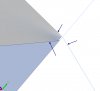
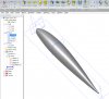
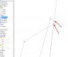
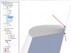
The attached file contains a wing tip for an aircraft. The top half was successfully lofted using sketch 1 and 2 with 3d sketch 1 used as a guide path.
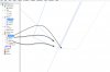
The lower half will not loft using the same tecnique with sketch 2 and sketch 4 and a guide path of 3d sketch 2.
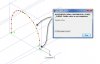
I tried using sketch 1,2, and 4 with a guide curve that followed the same path as 3d 1 and 2 combined, but that did not work either.
Where am I going wrong.

Thanks for any help
Leif
 

Attachments

  • Helio Wing Tip 2.stp
    244.7 KB · Views: 41
  • Loft Failure.jpg
    Loft Failure.jpg
    306.9 KB · Views: 40

Ralf

Alibre Super User
Hi Leif,

Please take a look at the sketches of Loft <1>.
This is the first required correction.
.
 

Attachments

  • Loft--1-1.jpg
    Loft--1-1.jpg
    102.3 KB · Views: 21
  • Loft-1.jpg
    Loft-1.jpg
    144.3 KB · Views: 28

Ralf

Alibre Super User
Loft<1>
Sketch<1> has a length of: 18 and Sketch<2> has a lenght of: 17 63/64
.
 

Attachments

  • Loft-Sketch-2.jpg
    Loft-Sketch-2.jpg
    60.3 KB · Views: 30
  • Loft-Sketch-1.jpg
    Loft-Sketch-1.jpg
    62.1 KB · Views: 27

Ralf

Alibre Super User
Leif,

In order to use the Loft feature, it is necessary to use accurate 2D Sketches and Guide Curves.
Please take a look:
.
 

Attachments

  • Loft-Sketch1-2-3.jpg
    Loft-Sketch1-2-3.jpg
    91.9 KB · Views: 28
  • Loft-Sketch1_2_3.jpg
    Loft-Sketch1_2_3.jpg
    216.9 KB · Views: 36

pc-6

Member
Ralf
I have redrawn everything as accurately as I can and have analized all sketches and have found no problems.
As you can see it will still not loft properly.
Perhaps there is an issue with the 3d guide curve. I used this methode to create it so that I could intersect it with the three 2d sketches, which I had installed nodes on in order to do this.
When I zoom in very closely on the failed loft at the end of the 3d sketch where it meets the 2d sketch I see some small tails, but I think those might be due to funny graphics because i have zoomed in so close.
Am I taking the correct approach with the 3d sketch? What am I missing.

Thanks for your patience
Leif
 

Attachments

  • Helio Wing Tip 4.stp
    66.3 KB · Views: 27

Ralf

Alibre Super User
pc-6 said:
Ralf
I have redrawn everything as accurately as I can and have analized all sketches and have found no problems.
As you can see it will still not loft properly.
Perhaps there is an issue with the 3d guide curve. I used this methode to create it so that I could intersect it with the three 2d sketches, which I had installed nodes on in order to do this.
When I zoom in very closely on the failed loft at the end of the 3d sketch where it meets the 2d sketch I see some small tails, but I think those might be due to funny graphics because i have zoomed in so close.
Am I taking the correct approach with the 3d sketch? What am I missing.

Thanks for your patience
Leif

Hi Leif,

You've made ​​some good progress with the sketches. :)
Now we just need to create a continuous Guide Curve (3D Sketch).
Please take a look:
.
 

Attachments

  • 3D-Sketch-Guide_Curve.jpg
    3D-Sketch-Guide_Curve.jpg
    156.3 KB · Views: 39

Ralf

Alibre Super User
Leife,
I have created a new continuous Guide Curve (3D Sketch) , based on yours.
Now it works. :D
.
 

Attachments

  • Helio_Wing_Tip_5.AD_PRT
    914 KB · Views: 34
  • Loft-with-3D-Sketch.jpg
    Loft-with-3D-Sketch.jpg
    352.8 KB · Views: 51

pc-6

Member
Ralf

After looking at your post and what you did to make the guide curve work I corrected my previous one as a excercise, just like you did.
I think now I understand how that works.
Thank you for helping me understand the process.

Oldbelt
Thankyou for the inspiration. It is nice to see other modelers work. It is also a great resource, as we share some of the same challenges.

Leif
 
Top