What's new

Loft Problem

pc-6

Member
As can be seen in the screen shot there is an inconsistencey in the surface of this loft. In the middle of this wind shield the loft follows the guide curve on one side and then not on the other. I have tried using the guide curves globally and locally with the same result. I have left the local selection for the screen shot as it makes it very obvious as to what the problem is.

A little help with this would be much appriciated.

Thank you in advance,
Leif
 

Attachments

  • PC-6 Wind Screen.JPG
    PC-6 Wind Screen.JPG
    145.2 KB · Views: 28
  • PC-6 B1-H1 Windscreen Forum example.stp
    234.3 KB · Views: 15

Ralf

Alibre Super User
The problem is caused by: Sketch -> Bottom of WS
.
 

Attachments

  • Sketch-over-2.png
    Sketch-over-2.png
    4.8 KB · Views: 666
  • Sketch-over-1.png
    Sketch-over-1.png
    7.8 KB · Views: 667

pc-6

Member
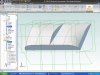
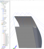
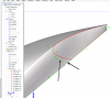
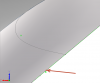
OK I have cleaned everything up and the loft seems to work fine but I still have that uneven surface at 3D sketch 6. When I cleaned up the "Bottom of WS" sketch I took out one half of the spline with the small segment of a straight line. I then mirrored the remaining side over so now there is only one point at the middle of the sketch.

I am unable to shell it out ( I just get an error message.) This shell should be done before I do my extrude cut of sketch 4, which is also giving me problems. I presume the problem with the shell operation relates to the step produced at 3D sketch 6.
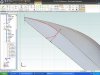
In sketch 4 it will cut just fine when I use line 1, line 3 and b spline 2, but when I try and modify the sketch with line 4 and extend line 2 too intersect I cannot trim the spline and line 4 properly. I know this seems so basic but I guess I have been looking at it so long I am going blind to the simple solution. I have attached a screen shot of the problematic sketch 4. Also attached is an updated file with the fixed loft.

Summary; How do I fix this inconsistencey at 3D sketch 6? What do I need to do to be able to perform the shell operation? How do I fix sketch 4 ?

Thank you,
Leif
 

Attachments

  • PC-6 Wind Screen Sketch 4 cut.JPG
    PC-6 Wind Screen Sketch 4 cut.JPG
    127.4 KB · Views: 7
  • PC-6 B1-H1 Windscreen Forum example 2.stp
    309.3 KB · Views: 6

Ralf

Alibre Super User
Leif,

"Sketch <4>" is not a closed sketch.
.
 

Attachments

  • Sketch-4-1.png
    Sketch-4-1.png
    73.1 KB · Views: 7
  • Sketch-4.png
    Sketch-4.png
    124.8 KB · Views: 11

pc-6

Member
I realize it is not yet a closed sketch. I have been trying to modify it from its original shape that matches what you have shown in your second posted image. The updated sketch should include line 4 which will cut off the lower part of the spline. I have started this modified drawing but it won't allow me to trim it properly.
 

Ralf

Alibre Super User
There is a very short line segment in your sketch.
With "Analyze" you can check your sketches.
.
Please take a look, here is your problem.
.
 

Attachments

  • Analy-1.png
    Analy-1.png
    73.6 KB · Views: 13

Ralf

Alibre Super User
...and here is your 3D Part in V2012 (14056).
.
 

Attachments

  • PC-6 B1-H1 Windscreen-new.AD_PRT
    1,017 KB · Views: 11

pc-6

Member
Ralf

Thank you so much for fixing this.
What needed to be corrected to make this work properly?

Leif
 

Oldbelt

Alibre Super User
Leif look here, your windscreen in 4mm. sheet material.
It's not true, it can't be made in sheet mat. because the od sharp edges at the upper corners.
I don't believe the original airplane have this.
 

Attachments

  • PC-6 B1-H1 Windscreen-oldbelt-2.jpg
    PC-6 B1-H1 Windscreen-oldbelt-2.jpg
    35.2 KB · Views: 13
  • PC-6 B1-H1 Windscreen-oldbelt-2.AD_PRT
    1.3 MB · Views: 8

pc-6

Member
Oldbelt
You are correct, the original did not have this. However, this part creation will be used to make a plug which will be used to vacuum form the windshield. This will then be cut to match the shape of the full size. This cut will eliminate the portion that has the sharp corners.

Leif
 
Top