What's new

Lofting and guidecurves. Need some help please.

Elrick

Senior Member
Hi there,

Ive come to a point where I need some help. Im busy with an aircraft canopy. The thing is that its already been drawn with other CAD software. I need to redraw it with Alibre. So far I got over a lot of obstacles and challenges, but cant seem to get this right. Maybe some one with more experience and knowledge could help me perhaps?

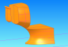
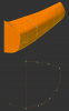
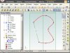
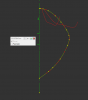
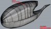
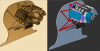
I realize theres 2 ways to loft the canopy that seems possible and accurate. The first part of the canopy lofted quite well with 2 guide curves only. Once you use more, it becomes deformed. There are two profiles I used for the front of the canopy. And now two for the Back of the canopy. But it seems the lofts need much more guidance. In the file there are lots of horizontal guide curves with some vertical profiles (taken and adjusted from the original drawing). I will attach a pic of what I achieved and another for what needs to be achieved.

Any advice or references to other places where people had similar challenges will be appreciated :)
Thanks
Elrick
 

Attachments

  • Cannopy Assembly (1).jpg
    Cannopy Assembly (1).jpg
    79.4 KB · Views: 17
  • C-WolfCanopy.jpg
    C-WolfCanopy.jpg
    62.9 KB · Views: 26
  • ForumFile.AD_PRT
    511 KB · Views: 18

RCH_Projects

Alibre Super User
Hi Elrick,

Given your problems with design as-is, I can only recommend that you break the canopy elements into separate parts (with common profile elements at attachment points and keeping the XYZ positions fixed).

Then bring the components together in a "boolean" build or assembly.

Regards,

Roger
 

Elrick

Senior Member
Thanks Roger. I managed to improve the lofting a bit. The front half were quite simple since the 2 profiles I used for the lofting have similar shapes (used a few guide curves). The other half demanded more guide curves since the two profiles looks nothing alike. I am happy with the shape but not satisfied.
 

Attachments

  • Canopy Assembly (2).jpg
    Canopy Assembly (2).jpg
    79.6 KB · Views: 20

Elrick

Senior Member
So, by "chopping" the whole sketch up with the extrude cut tool, I got the best sketches and also pefect points for my guide curves from the original part (drawn by solidworx). But for some reason, I got a lot of errors when two sketches falls on the same plane. I use the project to sketch and copy (ctrl+C) a lot to keep the same profiles when lofting. But then you get those irritating errors. So I learned, a while after drawing these, that its better to create a plane, 0.1mm away from your last loft the overcome interference and errors. Now I only hope I will be able to stitch these section together at a later stage...
Further more, I hade to make two different sketches and assmble them cos of the errors. From there I exported it as a SAt and imported it again to obtain one part...

Hope this helps someone :D
 

Attachments

  • 1.png
    1.png
    165.2 KB · Views: 5
  • 2.png
    2.png
    101.6 KB · Views: 5

Elrick

Senior Member
I have a problem and need to know if there are more simple ways than what Im aware of. To manipulate profiles/splines in lofts are limited. In attached pic I have marked a point I just need to move down a couple of millimeters but GMD doesn't have the option to move the start and end point of a spline. The problem is that when you manipulate, or redraw, one profile in a loft it usually crashes because one or more guide curves loses its intersection with the changed profile. Then you have to redraw all the guide curves which is a real big pita! I know I could move the profile down but I want to stretch it without touching the top point position..? Is this possible?

Thanks
 

Attachments

  • Profile manipulation 1.1.png
    Profile manipulation 1.1.png
    189.1 KB · Views: 6

Elrick

Senior Member
It would be beneficial if the intersections were marked in 2d & 3d sketch mode. When you need to make changes to the profiles you will have a better idea of where your 3d guide curve is going when you move the control points in the 2d spline. What would be even better is if your 3d spline dominates the 2d spline it intersects!? That way you could have better control over lofting. Any one who agrees?
 

Attachments

  • Profile manipulation 1.2.png
    Profile manipulation 1.2.png
    174.6 KB · Views: 7
  • Tail 1 OH.zip
    280.6 KB · Views: 1

TylerDurden

Alibre Super User
Elrick said:
...GMD doesn't have the option to move the start and end point of a spline....
Hi,

It seems you can make the ends of the spline mobile/editable, by first inserting a reference figure and starting/ending the spline on the nodes of the reference figure.


HTH,
 

Attachments

  • Spline control.AD_PRT
    221.5 KB · Views: 7
  • SplineControl.jpg
    SplineControl.jpg
    63.4 KB · Views: 8

NateLiquidGravity

Alibre Super User
You can also do Sketch>Insert>Point while in a 2d sketch and pick the nodes (one at a time and apply). This will give points that sticks to the sketch and updates its position.
 

Elrick

Senior Member
Cheers gents!

Tried this way but the center reference wont option for dimensions. I'll need to constrain one end and the center reference line vertically. To stretch it in a similar way you shared Tyler. Seems like the only way to make fast easy modifications to a loft. I should probably have checked to make sure those specific points had intersected a perfectly curved spline from the side view. Seems like another step NOT to avoid when lofting!

I've made some good improvements on the original drawings. Its been day in day out. I really wish these boundaries could be expanded in Geomagic Design!

On a side note, MoI is starting to look more attractive each day. It handles splines much differently. But these "reversed engineering" ways wont jam very well over there. Other gents from SW are also looking for better surfacing software on MoI's forum. Every package has its stuff that makes modeling better but always shorts something. These companies should melt together and invent something universal!? Affordable to everyone.

Any other suggestions?

Thanks
 

Attachments

  • Okop 1.1.png
    Okop 1.1.png
    12.8 KB · Views: 387
Elrick,

Assuming that you are working with loft lines that are planar in nature, one approach would be to create loft section plans to control the position (usually called a station) of each sketch. My approach would be to start by defining a bunch of variables within the Equation Editor -- say: a_b_Sta_1, a_b_Sta_2, etc. Then I can reference a_b_Sta_x in the appropriate entry in a Reference Point coordinate definition and set up (say) start point, mid point, and end point positions that would control those three points in my curve. This gets a bit messy if one is dealing with station planes that are not parallel to the cardinal planes.

Traditional lofting was a 2D representation of 3D surfaces that was first standardized by a conference held in Glasgow (Scotland) early in the 19th century (1804, if my memory is correct). The original specification was that Waterline, Buttline, and Station values be set on 6 inch or 12 inch spacing. (The aerospace industry then standardized on 5 inch and 10 in spacing sometime in the 1930's and 15 cm and 30 cm was added sometime after that.) Once a contour was established in (say) the Buttline-Station plane, it could be projected across the Waterline spacing and used to generate a (say) Waterline-Station set of curves. Whipsawing back & forth between (say) Buttline-Station planes and Buttline-Station planes (and actually cutting and fitting "headers" to wireframe the shape) allowed a shape to be (relatively) quickly defined and tested. It is basically the approach I use to create aerodynamically & hydrodynamically optimized shapes today -- I just substitute a rendering for cutting and fitting "headers."
 

Elrick

Senior Member
Thanks Lew! I think these ways are to be considered before starting. Things are getting messy. Hard to keep everything organized as it already is. One lesson I learned is to create a main file/drawing just for contour or reference lines. And use Ctrl+C - Ctrl+V to copy the profiles into other drawings. After changes were made to the curves project them back to the reference/main drawing and "over write" or delete the old profiles. It gives you some sort of deviation analysis to compare your lofts with. The 3d measurement tool and reference nodes becomes very handy in this case.

If I understand correctly, the way you recommend seems a bit complicated. Since the vertical profiles alone would roughly need 3000 co-ordintes. Its the same way the canopy were designed in SW.

Lew_Merrick said:
control the position (usually called a station) of each sketch

I draw each profile on its own defined plane which controls the position. Is this what you mean with "loft section plans"?

Lew_Merrick said:
loft lines that are planar in nature

You got me a bit curious and thinking, can a 3d spline be constrained to a planar surface and still intersect profiles when lofting? Or do you mean a 2d spline on a plane at a strange position intersecting the profiles?

Do you know a website or piece to help familiarize with some of the term you use? Or some visual demonstrations? I dont use the "Aircraft Station Coordinate System"...


Thanks
 

Attachments

  • Fuselage 1.2.3.png
    Fuselage 1.2.3.png
    1.7 MB · Views: 7

Elrick

Senior Member
Btw, GMD could improve the lighting options or implement a "zebra environment". Its double work to export the lofts to other software for surface analysis. Im seeing flaws in my loft which I couldnt have spotted in GMD.
 

Elrick

Senior Member
Had a second shot at your shared way Tyler. It seems to work!! Managed to constrain the center reference line vertically and one end. Dont know what went wrong with the other one I tried. But I will need to restart/redraw all the profiles again when trying this way. Not very keen atm. Will test it on the pontoons when improving them and give some feedback.

Cheers
 

TylerDurden

Alibre Super User
Glad to hear it's of some use.

I went back to the help files to review splines and have only a slight understanding of the merits of each method. Case examples would be nice for each, i.e. why one method might be better than another.

Here is a topic I started to request insights from other users:
viewtopic.php?f=10&t=17963
 
Elrick,

In my view, 3D Splines are for things that are tied together with known & controllable points such as pipe or wiring runs and (coincident point constrained) lofting guide curves and the like. Lofting, as defined in older versions of French's Engineering Drawing and the McDonnell Aircraft Company's Loftsman's Handbook (which, I believe, was "in print" into the 1950's -- though my copy was from sometime in the 1930's) is based on stitching together planar geometry into a 3D volume. Under those conditions, I fail to see the advantage of using a 3D Spline to control an essentially 2D shape!

My example was based on using longitudinal Stations (because that is what 90% of all the lofting I have done is based on), though using Waterlines (i.e. horizontal planes) or Buttlines (vertical planes parallel to the structure's centerline) are not uncommon. The issue is insuring that the intersection of these various curve entities are exactly true -- and not "off" by some nearly infinitesimally small amount.

There are actually about 25 curve forms (i.e. mathematical equations for different curve types) used in formal & traditional lofting. GMD (and Alibre before) provide only a generalized cubic spline form (which I believe is a B-Spline) for such work. MOI and other freeform modelers make use of Non-Uniform Rational B-Splines (more generally known as NURBS) -- which have their own issues when one is working in a turbulence minimizing environment. When working on a hypersonic vehicle (as I did a few years back) it is essential that one do the work using Catia in order to be able to accurately define the lofting curves through Catia's extensible entity dataset provision -- and even then, it is more "fun" than anybody with a shred of sanity left should attempt...
 

Elrick

Senior Member
Thanks for clarifying Lew!

I too use longitudinal stations most of the time. The but-line- & waterline-stations are used to guide the lofts by 3d Guide Curves/splines and help to spot significant differences from the original design. Organic or semi planar ways. Would like to see how 2d Splines will react in lofting! Never tried 2d guide curves. I fail to see how 2d sketches are beneficial to organic shaped lofting. I cant debate or argue since I haven't tried it before. This is called "guide rails" in MoI and probably the only reason so far why I feel MoI cant handle lofts as good as GMD. Lofts divided into sections doesn't seem promising over there. But I am going to try it!

When I came to think about it more clearly, 3d spline constrained to a planar surface basically makes it a 2d spline. But it will simplify the process when picking the intersections manually rather than using reference points. Dont think this recommended way of yours will work in my case. See attachment "Iso Curves". Dont know how well I could describe this. It could be related to the Gyro Scope. If you turn the camera around an axis 15° at a time , enter 3d sketch mode, and draw a guide curve intersecting all the profiles in a straight line (exactly on top of the axis you rotated about) you will find a very organized loft. [ISO Curves looks "natural" and not mechanical(splines parallel to your three default planes)] Natural, I believe, is the way to go with organic shapes/lofts. I will make a visual demonstration later to demonstrate.

Lew_Merrick said:
The issue is insuring that the intersection of these various curve entities are exactly true -- and not "off" by some nearly infinitesimally small amount.

This is why I never thought about trying it. I cant imagine how difficult this must be. Seems easy when your splines are parallel to your default planes but if your spline aren't parallel to any of these planes youre going to need a gifted mind to calculate it mathematically. I think :)

You probably know X-Plane? We used this platform to test our design.
 

Attachments

  • Iso Curves 1.2.2.png
    Iso Curves 1.2.2.png
    565.5 KB · Views: 10
  • Guideless Loft.png
    Guideless Loft.png
    300.9 KB · Views: 2
  • Engine Render Comparison.png
    Engine Render Comparison.png
    1.3 MB · Views: 12
I can't share the design data, but I have done extensive lofting of various devices that must fit various parts of the human anatomy quite closely using non-parallel basis for lofting geometry. What I tend to do is to layout the basis planes in a spreadsheet and calculate my control points mathematically therein. I can then copy and paste the values (to 64-bit precision) to my basis planes in GMD. I assure you that this is "fun" of the greatest degree! It makes FLOFT coordination look simple...
 
Top