What's new

Lofting Help

kcoffield

Member
Need some help lofting fellas. The attached is the center section of a V8 automotive intake manifold. There are 8 pairs of port windows that need to be connected by loft. I have all of the sketches for the lofts in the correct positions except for two (more on that later). Attached is the file as far as I could get. The lofts are just Alibre generated from face to face but I need to make them guided centerlines lofts that connect to the centers of the respective loft sketches (port windows), but along the guide path centerline

I’ve tried a number of ways to create a 3D spline guideline but not even close to success. I was think I could generate them by a projecting a 2D spline sketch that connects the port centers created in the XY plane onto a cylindrical surface of the parting line, but I don’t know how to do that and am open to any suggestions and guidance. I suspect the ends will need to be constrained perpendicular as they approach the respective lofting faces/sketches to be a suitable lofting centerline guide line. I never did succeed on my last ceneter line guided loft.

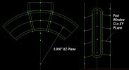
The Plenum port windows on runners 1 & 5 really need to be repositioned. Ideally I would like to project them onto the lofted surface/radius where they interface with the plenum as opposed to just being located on same plane as the rest of the plenum port windows. As a contingency, maybe create a plane tangent to that surface for those port window sketches.

This model is the exterior surface. I thought I’d make the solid, fillet it, then shell it inward with ¼” wall, then part it on that 5.916” radius cylindrical center/parting line so I can machine the internal features.

I’m willing to put some real time and effort into this model because I need to make a number of similar variants, and eventually I’d like to make a real parametric model that would update with changing size and position of the port windows and a couple other features.

If I could see the method to execute one centerline guided loft, I could probably figure out at least the other 6, and maybe those last two on Runners (1 & 5).

Any and all help greatly appreciated.

Best,
Kelly
 

Attachments

  • JB Inline Spider with Straight Lofts Runners.AD_PRT
    1.9 MB · Views: 9
  • Spider Comments.jpg
    Spider Comments.jpg
    105.2 KB · Views: 23

Oldbelt

Alibre Super User
Please sketch on a piece of paper how this object look, Your explanation is not understandable.
 

kcoffield

Member
Please sketch on a piece of paper how this object look, Your explanation is not understandable.
The part actually looks very similar to that shown in the attached model of the first post. The lofts just are not the correct shape. Let’s see if I can simplify this.

1. I want to create a 3D spline that can be used as a centerline to (centerline) guide for each respective loft (labeled “runner”) in the model.
2. I’d like to be able to project sketches onto a surface for the sketches used in at least two of those lofts.

If I saw an example of how to create and use one of the desired loft guidelines, that would be helpful. Same for a method for projecting a sketch onto a surface.

Hopefully the pictures below along with the model attached in the first post will make this is more clear. The feature names used in the pictures correspond with those used in the model.

Best,
Kelly

Slide1.JPGSlide2.JPGSlide3.JPG
 
Last edited:

Ex Machina

Senior Member
Hey Kelly,

I saw your post and I am still not sure what you mean. Specifically, why you'd want to project, and project what onto what.

To be honest, you can design just the first runner and then mirror and pattern to get the other 7. Any parametric changes would be carried over.

For example, I see that the plenum sides are flat faces. So, you can sketch on them. Why would you project? And if you want your runners to have a consistent section from where they start to where they end, that would be better achieved with a Sweep. Finally, if your centerline just an arc, than it's a planar curve and can be designed to be what ever you like with a simple 2D sketch. What is the surface that you want to project onto to create your centerline?

Can you create a package of the part so we can see what you're shooting for? Maybe then we'll be able to help more.
 

kcoffield

Member
To be honest, you can design just the first runner and then mirror and pattern to get the other 7.
The runners are similar but they are not the same. Mirroring will not work. I need to generate a unique guideline for each of the 8 lofts.
For example, I see that the plenum sides are flat faces. So, you can sketch on them. Why would you project?
The front two runners need to intersect the curved face of the plenum, not the flat face(s). I did construct planes coincident with the flat faces to sketch on but they are only really suitable for 6 of 8 sketches in this example. I just used them for the front 2 because I didn't know how to place them on the curved plenum surface, thus the desire to project them.
And if you want your runners to have a consistent section from where they start to where they end, that would be better achieved with a Sweep.
The runners do not have a consistent cross section. They decrease in area by 25% from the plenum to the other end of the runner/loft. This is done for fluid dynamics and performance reasons and why the runners are lofts and not sweeps. It is common for the shapes to be different at each end of the runner so sweeps are not an option.
Finally, if your centerline just an arc, than it's a planar curve and can be designed to be what ever you like with a simple 2D sketch. What is the surface that you want to project onto to create your centerline?
It is not just an arc. It's a 3D spline because there is an offset between the centers of the lofting faces on the end of each loft/runner in the direction of the Y Axis. This can be seen in the XY plane. When viewed in the XZ Plane the center guidelines/spline(s) appear as an arc(s).
Can you create a package of the part so we can see what you're shooting for? Maybe then we'll be able to help more.
I'm a novice and don't know what a package is. Since I posted, I used the method described in this YT Video hosted by Alibre to generate the desired guideline for one runner (#6).


It basically teaches as I described above, sketches a spline/guideline shape as viewed in the XY plane, then thin extrudes that spline, deletes the extraneous surface so itis just a surface of no thickness and is moved to intersect with the cylindrical surface. The "project" command can then be used in 3D sketch mode to capture that intersection as a 3D spline.......which in my case is the desired guided centerline for the runner lofts. That's a lot of work to generate one line but I successfully did so to create the guideline for "Runner 6". However, the loft will not generate when I try to use that 3D spline as the guideline and gives no reason why. It just won't execute. In a previous post some time ago, Harold tried to help me and reading the Alibre documentation says the guideline must be normal to the faces of the loft. This may be my problem now but Harold constrained that guideline to be normal and it would still not work. I can dig that up if it would help.
Would this work for you?
I cannot open that because I have V25 and it is a later release. From appearance, unfortunately I would say no for the reasons stated above. Attached is the same file only with the 3D spline guideline I generated. Sorry it's kind of a mess but I was just seeing if I could loft from "PW6" to "Plenum Opening 6" using "6 3D Loft Guideline" 3D spline as the guideline. I cannot make it work. The centerline guided loft command will not execute. Can you loft along that centerline? Or understand why it will not?

Thank you very much for your reply and example.

Best,
Kelly
 

Attachments

  • JB Inline Spider with 3D Spline Loft Guide Test.AD_PRT
    1.5 MB · Views: 3

kcoffield

Member
Thiswas theprevious thread I was referring to.


It has a link in my post to a similar runner loft where I did not succed. In the thread, you'll note Harold mentions you cannot loft along a 3D spline guideline. However, It is done here successfully....just not by me!


...and here in this video at about the 8 minute mark he lofts on a arc guideline that is not perpendicular to loft faces.......but the guideline is not a spline.


....and then a loft along a 2D (but not 3D) spline at 12:30. I think JOKO is a member here.

Best,
Kelly
 

kcoffield

Member
I took a closer look at the test spline/guideline in the file in post 6 and it appeared that one end the guideline did not intersect one of the loft faces. I thought the ends had snapped to the reference points but apparently not. I fixed that and when I tried to guide the loft with that spline I got the perpendicularity error. The guided loft still will not generate but at least now there is a reason stated. I can try to make a short straight section of the spline at each end and constrain it perpendicular to each loft face but as mentioned above in the linked thread, even that failed in that previous example. So I guess I'll ask, has anyone here ever successfully executed a guided loft that uses a 3D spline as the centerline guide?

Tomorrow is a new day.

Explanation 4 Not Perpendicular.jpg
 
Last edited:

kcoffield

Member
Ureka!!!! I took a different approach. I created the 3D spline first making the ends normal to model objects they intersected, then used the plane along the sketch option to create planes normal to the ends of the spline. I sketched the loft faces on those planes and they successfully lofted along the 3d spline guideline. I guess I just wasn't able to constrain the spline sufficiently normal to the planes I was sketching the loft faces on without using the Alibre command to create planes normal to the ends of the spline. I'll do some work and see if I can get it to translate across my model.

Best,
Kelly
 

kcoffield

Member
I did succeed with the lofts and happy with the general appearance, but it won't shell or fillet. More to learn. I have 2 days of examples of what won't work for lofting with 3D spline guide curves but the only method that does work is creating the sketch planes for the lofting faces normal from the spline as described immediately above. Thanks for the help.

Best,
Kelly


Center Section Bottom.jpgCenter Section.jpg
 
Top