Rare Waves
New Member
If you have experience forming sheet metal parts accurately on a box-and-pan brake from Alibre flat patterns, I would like to hear your methodology.
Our parts are small (typically < 12”) and made of 5000-series aluminum alloy sheet of 0.040”-0.063” thickness. My goal is to succeed in forming 90-degree bends to reasonably tight tolerance (+/- 1/64”) on the first try. The purpose is prototyping, one-off jobs. I’d like to avoid having to make one, measure the error, trash it, sketch up the flat pattern, and then try again.
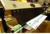
Now the specifics, please refer to "Bend formation reference.jpg". The pan and box brake, you are familiar with, it has a clamp edge and an apron edge. In practice the operator sets the distance between these lines to about 1.5MT, or ~0.10” if the workpiece is 1/16” thick.
We enter published K-factors and reasonable bend radii as the parameters. Then Alibre generates flat patterns from sheet metal parts, and for each bend the flat pattern has two lines plus a optionally displayed bend centerline.
We copy the lines from the flat pattern onto the sheet metal part accurately. Now, the brake operator clamps the part it in the brake, pulls up the apron, and forms the bend. Obviously the part must be positioned accurately in the machine or you obtain a flange of the wrong length.
But, that’s where it gets confusing. What I want to know is, when the brake operator has clamped the sheet in the brake and is about to form the bend, exactly how do the bend lines on the Alibre flat pattern relate to the position of the lines represented by the machine’s clamp edge and apron edge? Can you succeed in forming an accurate bend, for example, by fixturing the part with line A co-linear with the clamp edge? Or do you find it necessary to manually sketch in a 4th line, offset by some experience-based fudge factor, for the brake operator to visually line up co-linear with the clamp edge?
Our parts are small (typically < 12”) and made of 5000-series aluminum alloy sheet of 0.040”-0.063” thickness. My goal is to succeed in forming 90-degree bends to reasonably tight tolerance (+/- 1/64”) on the first try. The purpose is prototyping, one-off jobs. I’d like to avoid having to make one, measure the error, trash it, sketch up the flat pattern, and then try again.
Now the specifics, please refer to "Bend formation reference.jpg". The pan and box brake, you are familiar with, it has a clamp edge and an apron edge. In practice the operator sets the distance between these lines to about 1.5MT, or ~0.10” if the workpiece is 1/16” thick.
We enter published K-factors and reasonable bend radii as the parameters. Then Alibre generates flat patterns from sheet metal parts, and for each bend the flat pattern has two lines plus a optionally displayed bend centerline.
We copy the lines from the flat pattern onto the sheet metal part accurately. Now, the brake operator clamps the part it in the brake, pulls up the apron, and forms the bend. Obviously the part must be positioned accurately in the machine or you obtain a flange of the wrong length.
But, that’s where it gets confusing. What I want to know is, when the brake operator has clamped the sheet in the brake and is about to form the bend, exactly how do the bend lines on the Alibre flat pattern relate to the position of the lines represented by the machine’s clamp edge and apron edge? Can you succeed in forming an accurate bend, for example, by fixturing the part with line A co-linear with the clamp edge? Or do you find it necessary to manually sketch in a 4th line, offset by some experience-based fudge factor, for the brake operator to visually line up co-linear with the clamp edge?