What's new

Manifold exhaust ed

Elrick

Senior Member
Greetings my fellow draughtsman and aliens. I would just like to share my idea/design and get some ideas/help. I guess I've been a bit too complicated with this but how can you join two circular 2d sketches, without any dimensions, around obstacles? Where the two sketches needs to be shaped by bends x2 or 1.5 the radius. One thing which makes it so complicated is that you dont have planes to work with really. This is one solution I could think about. Not working 110% and not professional but thats what I would like to achieve! The file could be found here.

https://www.dropbox.com/s/m99516mtceuql ... tor%29.rar

Sweep and lofting is out of the equation. Please let me know if theres trouble downloading the file!

Hope this will help someone in the future!

Regards
 

Attachments

  • Exhaust.png
    Exhaust.png
    1.2 MB · Views: 48

mshideler

Senior Member
I am not certain how you could do this without a sweep feature being used in the end.

Sketch wise, once you have the two circle sketches where you need them I would maybe use a 3D Sketch Spline and connect the two centers of the circles. Add a few points to the spline just so you can move the spline around in all 3 axis if needed and maybe seeing the spline in 3D space running the path that you want actual tubing it might inspire a method that you want. It could be a few welded tubes bent in arcs and connected at various angles, or a single tube with multiple bends.

IF the 3D spline doesn't work for you then you could also do a 3D sketch with straight line segments and when you have a path of the centerline of the tube set then add the desired radii between the straight line segments and then roll the assembly around in 3D and see if it looks like you are going to get the desired output. You could use bits and pieces of the single 3D sketch to created reference sketches to create each portion of the tubing that you will be welding together.

just my two coppers
 

Elrick

Senior Member
Thanks you for your input mshideler! I did actually use your first method explained before I found out about the radii that needs to be 2x the diameter. But I heard about another practical method being used to bend pipes today. Sounds really cool! Something about outomated CAD machines that bends to your desired dimensions. Reckon the method that I thought we will be using is a bit older. But it makes sense that when you need to make 1 or 100+ engines a day you will need some special machines to keep up. (Im only helping out the engineers whose hands are full atm)

Your second mentioned "copper" is the alternative I was thinking about too. Its just very cloudy in my mind. Making 3d sketches with liniar lines seems very limited. Feels like all your lines should be parralel with the 3 drawing axes? No sense of angles? Wouldnt know cos I havent used this tipe of drawing yet. Only using splines when it comes to 3d. Wouldnt it look similar to that old 3d pipe screensaver? lol
 

Attachments

  • Exhaust Outlet.png
    Exhaust Outlet.png
    1 MB · Views: 20

mshideler

Senior Member
" Making 3d sketches with liniar lines seems very limited. Feels like all your lines should be parralel with the 3 drawing axes? No sense of angles? Wouldnt know cos I havent used this tipe of drawing yet. Only using splines when it comes to 3d. Wouldnt it look similar to that old 3d pipe screensaver?"

Using the second method does work well if you need less organic bends, which would be easier on a tube bender and as far as the parallel to the 3D axis - yes but since you can change the drawing plane with sketching in 3D. You can also dimension angles between straight sections in 3D so you can get pretty good control. But if you can just do the work visually and whatever process you are outputting to is ok with organic (for lack of a better word at this point) tubes, then go visual. But if you are using a new guy on an old tube bender the straight sections at various angles and radii might be best, or if you are mass producing them, That being said, I have no idea if there are fancy tube benders that are so automated that they are more like CNC tube benders. In other words, give them and tube that can be bent and the machine will do it all (assuming you don't make a bend that causes material to split or run too thin.

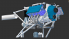
FYI - I think engines and the turbo systems are among my favorite models. You've got engines made with one set of design functions, mostly booleans. Then you get to see lofts, sweeps, etc. for various other shapes like the intake or bell housing, exhaust systems, etc. Love the powerplants. From my experience, they seem to use a multitude of modeling techniques.

<EDIT>

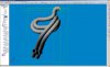
Brain-fart - also with the 3D sketch using straight segments, maybe adding dimensions for the angles between segments, and then adding the proper radii you can manipulate the sketch until it would indicate that your pipes go through the right areas in 3D space then create a separate 3D sketch and use a 3D spline to trace the line segment sketch so you can have a smoother pipe section - I say that assuming that there are assume pipe benders as compared to old school muffler shop style benders. In other words - the easiest sketch to move around via dragging or changing dimensions of you use dimensions, is the line segment type. Then use it for a reference for the spline style in a separate sketch.
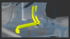
 

Oldbelt

Alibre Super User
For your inspiration
 

Attachments

  • Tube-exsample.jpg
    Tube-exsample.jpg
    100.9 KB · Views: 24
  • Tube-exsample (1).AD_PRT
    1.1 MB · Views: 8

Oldbelt

Alibre Super User
More.
 

Attachments

  • Tube-guide-Points-w-3d(1).jpg
    Tube-guide-Points-w-3d(1).jpg
    64 KB · Views: 17
  • Tube-guide-Points-w-3d(1).AD_PRT
    148.5 KB · Views: 11

Oldbelt

Alibre Super User
more.
 

Attachments

  • Exausttube(1).jpg
    Exausttube(1).jpg
    132.6 KB · Views: 26
  • Exausttube(1).AD_PRT
    1,016.5 KB · Views: 9

Elrick

Senior Member
Thanks for the advice mshideler and samples Oldbelt! Should be enough explanations and demonstrations to get a clear picture on the topic now. I gues the whole process mostly depends on the machine/person's ability to bend the pipes. (will give some feedback when we get to that stage)

Oldbelt, your tube by guide points is the one im familiar with! Used to cycle the sketch plane when drawing. One tip I could add here is to draw another spline ontop of your first one and delete the 1st one if you want to give your spline more freedom and to get rid of the "maintain accociativity" constraint. Not sure what its called
Your Exausttube(1) is the profesional way I guess :) The part thats challenging here is to work out the plane needed to create your 2d sketch path on for the sweep. Your plane needs to be flush with the direction in which the bend/arc points. If you have three points of the bend/arc you could add a plane. Think that solves the trick to the puzzle for me then :D

Thanks!
 

Attachments

  • Constraint.png
    Constraint.png
    1.7 KB · Views: 282

Elrick

Senior Member
mshideler,thanks! Im very excited about the end product ! Everything should be in place within the next 12 months. Still a lot of developement/innovation taking place.
 

mshideler

Senior Member
"I gues the whole process mostly depends on the machine/person's ability to bend the pipes. "

That can be a big factor as well. If you are using a shop you like but they are in the stone-age still (and you may not know this) then you end up going old OLD school.

I used an old school shop for years because I didn't know any better. Then I asked myself "what is going on? There has to be a better or faster way to get this stuff done." And surely there was. Sadly we had to cut the old school guy off who actually did lots of work for us, but he was also leaving himself to be antiqued or something because he wasn't going to change his technology.

I would think that there are automatic benders that can bend anything into any shape that you make assuming you don't use a material that thins out too much or rips open on a tight radius but I would also assume that that kind of shop could run what you send them through a simulation to see if you chosen material would handle it or if they have to make it in a few pieces and then weld it together.

Good luck!

If you get this done, post pics of the model and of the real deal!
 

Elrick

Senior Member
mshideler said:
I would also assume that that kind of shop could run what you send them through a simulation to see if you chosen material would handle it or if they have to make it in a few pieces and then weld it togethe

It does seem very logical! Think it should be called a Computer Aided Bender! lol

I just watched this video about a semi automatic tube bender. Looks like a very handy machine :)
http://www.youtube.com/watch?v=YgsvY-4-U4U
or search:
Baileigh MB-350 Mandrel Tube and Pipe Bender Exhaust Tubing Bending Machine
 
Top