What's new

Milling taper with AlibreCAM

jcdammeyer

Senior Member
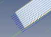
I can use 3D Horizontal finishing to create a tapered hole. But the outside perimeter ends up being horizontal no matter what I try. I must be missing something but what? The attached photo shows how the tool path goes down in a purely vertical fashion while the pat is tapered.

I've added the part. It's a simple 1/2" plate to be cut out of MDF. The inner hole has the taper. The perimeter doesn't. If I try any of the 3D operations it just mills out the hole even though I've selected the outer segments.

What's the trick?
Thanks
John
 

Attachments

  • NotTaperedCutting.jpg
    NotTaperedCutting.jpg
    76.7 KB · Views: 23
  • MotorMountPlatePattern.AD_PRT
    488 KB · Views: 7

Nick952

Senior Member
If I suppress or delete all the holes I get an "Unknown Internal Error" pop up message, when trying to generate the outer profile using 3D Horizontal Finishing.
Might be worth trying to redraw the model sketches and try again. If there is still a problem, contact MecSoft and they should help, even if you are not on maintenance with them.
 

jcdammeyer

Senior Member
I suppose someone from AlibreCAD should then investigate why you get an unknown internal error. I see that once in a while too. I save my work often. I'll try it here. Maybe the file was corrupted while uploading to this forum.
Thanks for trying.
John
 

Nick952

Senior Member
Hi John,

I've had a chance after my shift to have a play and even on a simple part I got the same error.
However after sketching a rectangular containment/drive region (larger than the cutter dia) on the base, the 3D Horizontal Finishing generated correctly.
Looks like it may be a bug in AlibreCAM, so might be worth reporting it to them.

Annotation 2020-03-09 223038.jpg

Nick.
 
Last edited:

Nick952

Senior Member
Not on my part, I just used the Draft Angle function in the Extrude, as did John in his design. I believe the Scaling he did, is to allow for shrinkage in the final casting.

Nick
 

jcdammeyer

Senior Member
I've asked a friend to import the drawing as a step file and generate the G-Code using Fusion-360. I'll report back what the results are.

I'll supress the scaling and see what happens but I agree that this appears to be a MecSoft issue. I've reported it to them. No answer back but then it's also been over 8 months since I reported that a feed rate on fourth axis should remain constant regardless of the part diameter and it's the rotational rate that should change as the diameter of the part changes. They said it's on their list.
 

Nick952

Senior Member
Just tried your part, using the same method as on my test part and with a .25" cutter got this:-
Edit:- Just checked and MecSoft have replied in the user forum.

Annotation 2020-03-09 234644.jpg Annotation 2020-03-09 235312.jpg
 

Attachments

  • MotorMountPlatePattern 2.AD_PRT
    598.5 KB · Views: 2
Last edited:

jcdammeyer

Senior Member
So my guess is that, although I think that the box stock should serve as a adequate boundary for this, it in fact doesn't. And rather than report that it can't it blows up instead. I'll cut up another piece of 1/2" MDF and give it a try.
Thanks.
John

upload_2020-3-9_17-17-11.png
 

KMoffett

Senior Member
Base Plate.PNG Just tried to make your base plate. My Z zero in the top. I used the base as one sketch, the large hole as a second sketch, and the screw holes as third sketch. Used chamfer to create the taper. Guessed on the dimensions. In AlibreCAM I Profiled the large hole to remove most of the material. Then Horizontal Finishing for the taper. Sectioned to show the taper.
 

Attachments

  • MotorMountPlatePattern-2.AD_PRT
    466 KB · Views: 1
Last edited:

jcdammeyer

Senior Member
When constrained, the horizontal finishing profiles the holes without needing to removed the middle. Extruding the module with draft lets one set the the ideal angle for the pattern so it pulls from the green sand correctly.
Ideally I'd set 3 degees of draft and then use a single pass 2D profile to remove the steps from the horizontal finishing. Using a ball end mill (router bit in this case) also makes the steps less visible if I didn't (which I don't) have the tapered too bit. I've been thinking of getting the tapered bit to try.
https://www.the-carbide-end-mill-st...ed-end-mill-3-tps-htc-96716-3fl-uncoated.html
 

KMoffett

Senior Member
Yup. I replaced the Chamfer with Draft and it worked fine. Is this for a casting pattern? I wondered because of the scaling.
Ken
 

jcdammeyer

Senior Member
Yup. I generally do the finished part as machined first. Then make a copy of that, scale it and in some cases change dimensions. For example scaling made the center hole larger so I had to reduce it in size so that once cast and machined the raised edge of the AC servo motor will register in the hole.

And yes I could have bought a piece of 1/2" aluminium and just milled it but where's the fun in that. And I think the price of the plate was 1.5 x one bottle of scotch.
 
Top