What's new

Modelling a ship hull

Spoors

Member
Hi all,
I have been using Alibre Design (now PE version) for a couple of years already to create models of small narrow gauge trains and to have them 3D printed. Once they have been motorised, tey are shown on small detailed diorama's at exhibitions. The shapes of these locomotives are quite straightforward, so I have not experienced any problems modelling them.

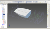
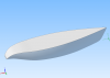
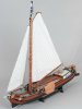
For a new diorama, I would to model a hull of a specific Frisian ship called a 'Skûtsje'. Below an image of a large scale model of one of these ships.


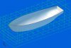
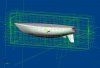
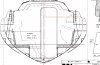
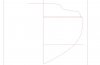
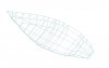
I have tried several ways to model the hull (as a solid, incl the deck) of this ship, but without any luck.
How should I approach this? The midsection is not too difficult, but I run into problems with the back and the front.
Unfortunately I have to do it directly in Alibre, as PE does not have a decent import function.

Anybody any ideas?

Cheers,

Jeroen
 

Attachments

  • Skutsje_af_1.jpg
    Skutsje_af_1.jpg
    107.6 KB · Views: 57
  • Skutsje_af_2.jpg
    Skutsje_af_2.jpg
    125.8 KB · Views: 62
  • Skutsje_af_3.jpg
    Skutsje_af_3.jpg
    120.8 KB · Views: 41

RCH_Projects

Alibre Super User
If ya got a decent export, Alibre has a good shot at it.
If allowed you can request PM volunteers to handle initial imports I'm sure.
What and how many conversions do initially need and when would you like them?

(I do have the advanced translate but I'm still on BETA.)

I favor spline imports, constraining to planes, axes, points for variability control and lofts.
Otherwise I reckon you have your prefered process and could teach me a few things. :)
 

Elrick

Senior Member
Hi Jeroen,

Here is some threads you could check out for some ideas:

viewtopic.php?f=10&t=14439
viewtopic.php?f=10&t=14577

Lofting and guide curves could be full of nonsense some times but once you get the hang of it it gets fun! If you need to make multiple lofts keep in mind that you cant let your planes or sketches fall in the same space if you want to use this same method like in threads above. This results in an error "Inconsistent face-body relationships". If your shape is constant you shouldnt have a lot of trouble otherwise you will need to use multiple lofts and guide curves (splines) to guide the lofting

If you have a better method or find one please share.

Goodluck
Regards
 

H-L-Smith

Senior Member
I think you are going to have to loft it in sections using "project to sketch" from the edges a completed section to start the loft curve for the next section, except for sections 3-7.

From the small graphic you have, the vessel appears to be symmetric about station 5 for two stations each way (3-7), which would mean you could do 5-7 or 3-5 and then mirror about section 5. From your remarks, it looks like you've figured that out. Have you worked with lines plans before? You have all the information necessary to lay out the shape (at least full scale) provided you also have the third component, called the table of offsets. Do you have that?

If you know about lines plans and the way naval architects lay them out, you'll know that in some views the direction of view is split about the centerline in both plan and section drawings. You should have all the section curves, but I don't see an indication of how far apart the sections are. It's got to be there somewhere, perhaps it's published with the table of offsets?

Also, the waterline curves are important guides to the hull shape. Do you recognize those curves in the plan view? I think this will be a challenging shape to loft in part because of the tumblehome (inward curvature) above the deck line and the unusual way the two halves of the vessel come together, almost with an inward crease, at the top rail on the bow. It might be easier to loft it in a conventional way without that cleft shape at the bow and "carve out" the final bow (stern too) shape with a sweeping cut, then shell the solid to a thickness (of the planks) for the final hull. That's just a speculative guess, however, hopefully an idea to try.

I've never used Alibre to loft a hull, and there are others her more skilled than I am in that area. However, the first thing you need to understand is how to extract information from what you already have in the drawings, assuming you're not familiar with lines plans. It's quite a fascinating process and you are looking at the literal origins of the lofting process - naval architecture. Creating the section curves with splines from the table of offsets would seem like a natural, first plan of attack for the lofting process to me. Obviously, you create one half of the section curve and then mirror it about the vessel centerline to get the whole curve, which is the joining of the two.

I hope this helps somewhat. I don't know what you know about lines plans now, so excuse me if I appear to be talking down to you and you already know the things I've written about.

Cheers,
 

Oldbelt

Alibre Super User
Hi Jeroen.
Import a bitmap of the hull to alibre in drawing mode .
Draw all the sectins copy and paste them to model space sketch mode .
Do the same with the water lines and sents.
The part is to big to upload I will send you a PM if your mail box can hold more than 2 mb files.
Give me a hint.
 

Attachments

  • Hull_B31(4).jpg
    Hull_B31(4).jpg
    290.3 KB · Views: 76

ptallgre

New Member
Hello
I am modelling a hull too. And without success. I really don't get the point how to use guide lines to show how the shape should be created with guide lines. Could someone send me a sample of some simple loft boss how the open or closed guide lines should be used. I think the previous post already has this information, maybe.
I attach the hull I have created. I cannot get it to one piece, due to some strange (for me) errors there. You'll see if you delete the middle part and try to use their lines to bow or stern parts. Of course I try to have the hull in one piece but I tried to split the problem to smaller pieces to get better idea what's going wrong. And I did not. Thanks for hints!


Pekka T.
 

Attachments

  • hull6.AD_PRT
    1.1 MB · Views: 16

Oldbelt

Alibre Super User
Hej Pekka.
I have looked at your file.
Some changes: sketch 1 is omitted and replaced with sketch 21 a sma..al triangle, you already had made.
Lofted in 3 sections, a one piece go isn't possible.
Your sections is to uneven in form, section 12 as an exsample is made of a soft rounded sketch,
but section 11 and 13 has a flat surface, its to complicated to calculate.
I have removed the Keel at the aft sections to simplify. Can be added after lofting of the hull.
The black lines show Alibres confusion. They also indicate that your hull won't be "fare".
You must create some sent's and make 3D guide curves throught the sections at this sent planes.
This will control the form and the points at your sketches will hopefully be ignored.
 

Attachments

  • hull6-Oldbelt[1].jpg
    hull6-Oldbelt[1].jpg
    146.4 KB · Views: 27
  • hull6-Oldbelt[1].AD_PRT
    1.8 MB · Views: 19

Oldbelt

Alibre Super User
Hej Pekka.
How to get the sections from paper to sketch plane in model space.
Insert the bitmap and draw. Edit >select all > copy, open a sketch plane in modelspace, paste.
Finish the section so it is possible to extrude a thin section. This can be scaled if needed.
After scaling, project sketch to the same plane and delete the first extruding (and the scaling).The right side is sketched with a red line.Ready to select all, copy and paste to a sketch in model space.
 

Attachments

  • SectionBMP-as-sketch.jpg
    SectionBMP-as-sketch.jpg
    224.7 KB · Views: 26
  • SectionBMP-as-sketch-to-modelspace.jpg
    SectionBMP-as-sketch-to-modelspace.jpg
    50.6 KB · Views: 17

ptallgre

New Member
Thanks for advices, but... still open questions

The removed "keel" is part of the hull, it is an IOR-class boat, Danish X-95.


You must create some sent's and make 3D guide curves throught the sections at this sent planes.
This will control the form and the points at your sketches will hopefully be ignored

Can you attach a sample file of these 3d guide curves? I don't get the picture how to use them.

Br, Pekka
 

Oldbelt

Alibre Super User
Hi Pekka.
I have look in detail at your hull6.AD_prt file.
The result of this is the birdcage (BC) in this picture.
I have made a couple of 3D curves: the rails, deck line, keel line and a couple of waterlines.
The part is here :Open it and look at from different directions.
You can see that a fair hull can't be made with the sections you have.
I don't know where from you got those sections, but it is very unprecise and some of them have sharp "corners".
To have succes with hull design, you need to start with a smooth BC and iterativ adjust sections and BC to each other.
Then you maybe can loft without problems.
 

Attachments

  • hull6-BirdsCage.jpg
    hull6-BirdsCage.jpg
    124 KB · Views: 30
  • hull6-Birdscage.AD_PRT
    503.5 KB · Views: 27

ptallgre

New Member
Ok, thank you very much. I think I got the point birdcaging the object.

The dimensions for the hull are from hand-made measurements made in -80's. These are the 'official' measures used through decades for handicap. The lines I have drawn are already smoothed, the original are even worse. And to remember, the hull IS odd shaped, the bottom is more or less drawn by ruler.

I'd like to have it 3D printed, nice hobby during winter time to learn Alibre, too.

Hälsningar till Denmark!
 

ptallgre

New Member
Basics lacking... How have you re-created the sketch 4 to sketch 22?
ctrl+C ctrl+T with some suitable constrains?

Pekka
 

Oldbelt

Alibre Super User
No i have adjustded them to fit to the master curves, those curves are a mean of your sections "corners". Your sections width and hight are adjustded to fit.
This gives the 3-D guide curves later created throught the sections a proper fair form. But your sections is very bad an unprecise.
A waterline section shows that a lot af adjustments are nessasery to your sections for make a nice and fair hull.
 

Attachments

  • hull6-Oldbelt-v2-MasterCurves [1].jpg
    hull6-Oldbelt-v2-MasterCurves [1].jpg
    90.1 KB · Views: 24
  • hull6-Oldbelt-v2-Loft based at mastercurves [1].jpg
    hull6-Oldbelt-v2-Loft based at mastercurves [1].jpg
    120.9 KB · Views: 20
  • hull6-Oldbelt-v2-Waterline-section [1].jpg
    hull6-Oldbelt-v2-Waterline-section [1].jpg
    118.2 KB · Views: 20

Oldbelt

Alibre Super User
Pekka.
Here are the Part file, hope you get a proper result,
but there are still a lot a work in this project.
Good wind.
 

Attachments

  • hull6-Oldbelt-v2 [1].zip
    1.1 MB · Views: 22

GIOV

Alibre Super User
I try to improve the hull but I get so many messages that frustrate me to get a good result in Alibre Gemagic Loft...
1.-SKIN_SELF_INTERSECTION: Self intersecting or cusping surface found. (ext)
2.-ACISERROR_INVALID_BODY_RESULT: Operation - The Feature results in an invalid Body.
3.-SKIN_BAD_UV_SKIN_DIR: Surface U and V are in the same or opposite direction. (ext)
I review many post regarding to these messages but I don't understand very well.
I hope have Step by Step the correct procedure.


Date: Tuesday, April 29, 2014 11:35:00 PM
Alibre Design™ Expert 2012
Alibre Design Version:[ PRODUCTVERSION 14,0,4,14056 ] 32-bit
Microsoft Windows NT 6.0.6002 Service Pack 2
Processor Information: Intel(R) Core(TM)2 CPU T5300 @ 1.73GHz
Number of Processors: 2
Microsoft .Net Framework
4.0.30319.1022
 

Attachments

  • Hull Yacht.AD_PRT
    1,011 KB · Views: 12
  • Hul Yacht Loft Issue.png
    Hul Yacht Loft Issue.png
    167.8 KB · Views: 20

bigseb

Alibre Super User
GIOV said:
I try to improve the hull but I get so many messages that frustrate me to get a good result in Alibre Gemagic Loft...
1.-SKIN_SELF_INTERSECTION: Self intersecting or cusping surface found. (ext)
2.-ACISERROR_INVALID_BODY_RESULT: Operation - The Feature results in an invalid Body.
3.-SKIN_BAD_UV_SKIN_DIR: Surface U and V are in the same or opposite direction. (ext)
I review many post regarding to these messages but I don't understand very well.
I hope have Step by Step the correct procedure.


Date: Tuesday, April 29, 2014 11:35:00 PM
Alibre Design™ Expert 2012
Alibre Design Version:[ PRODUCTVERSION 14,0,4,14056 ] 32-bit
Microsoft Windows NT 6.0.6002 Service Pack 2
Processor Information: Intel(R) Core(TM)2 CPU T5300 @ 1.73GHz
Number of Processors: 2
Microsoft .Net Framework
4.0.30319.1022
GIOV, the horizontal lines (i.e. the deck) consist of two to three segments each. Delete these segments and draw just one line across.
 

Attachments

  • Hull Yacht.png
    Hull Yacht.png
    43.8 KB · Views: 10
  • Hull Yacht.zip
    36.5 KB · Views: 13

GIOV

Alibre Super User
Thanks bigseb,
I did you suggestion but in the Scketch 9 I still have a message.
1.-SKIN_SELF_INTERSECTION: Self intersecting or cusping surface found. (ext)
I don't have idea what is wrong. The Scketch is close correctly.


Alibre Design™ Expert 2012
Alibre Design Version:[ PRODUCTVERSION 14,0,4,14056 ] 32-bit
Microsoft Windows NT 6.0.6002 Service Pack 2
Processor Information: Intel(R) Core(TM)2 CPU T5300 @ 1.73GHz
Number of Processors: 2
Microsoft .Net Framework
4.0.30319.1022
 

Attachments

  • Hull Yacht 02.jpg
    Hull Yacht 02.jpg
    126.4 KB · Views: 18

GIOV

Alibre Super User
Ok,
It wasn't easy but I reach the hull. :D


Alibre Design™ Expert 2012
Alibre Design Version:[ PRODUCTVERSION 14,0,4,14056 ] 32-bit
Microsoft Windows NT 6.0.6002 Service Pack 2
Processor Information: Intel(R) Core(TM)2 CPU T5300 @ 1.73GHz
Number of Processors: 2
Microsoft .Net Framework
4.0.30319.1022
 

Attachments

  • Hull Yacht 03.jpg
    Hull Yacht 03.jpg
    123.2 KB · Views: 26

bigseb

Alibre Super User
GIOV said:
Thanks bigseb,
I did you suggestion but in the Scketch 9 I still have a message.
1.-SKIN_SELF_INTERSECTION: Self intersecting or cusping surface found. (ext)
I don't have idea what is wrong. The Scketch is close correctly.


Alibre Design™ Expert 2012
Alibre Design Version:[ PRODUCTVERSION 14,0,4,14056 ] 32-bit
Microsoft Windows NT 6.0.6002 Service Pack 2
Processor Information: Intel(R) Core(TM)2 CPU T5300 @ 1.73GHz
Number of Processors: 2
Microsoft .Net Framework
4.0.30319.1022

Forgot to mention that I edited the underside (arc) segments of sketch 9 too. Instead of three separate segments for the underside of the hull I replaced them with one spline.
 

Oldbelt

Alibre Super User
Hi All out there.
Ship hulls and aero objects procedure :
The finished Part.The last steps (10-18) in the procedure is in next mail
 

Attachments

  • TestHull (1).jpg
    TestHull (1).jpg
    163 KB · Views: 20
  • Step-1-9.zip
    1.1 MB · Views: 30
Top