You are using an out of date browser. It may not display this or other websites correctly.
You should upgrade or use an alternative browser.
You should upgrade or use an alternative browser.
Modelling a "Turning Feed Screw"
- Thread starter ynnek
- Start date
Lew_Merrick
Guest
Ynek,
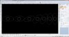
There is not enough information posted for me, at least, to grasp the nature of your problem. You posted a picture of that I interpret to be stages along a (lofted?) variable pitch feedscrew. You then ask for a matched set of feedscrews that will turn the (a?) container 90°. There is not enough information contained in that description to establish a Statement of Work to follow. That makes it somewhat hard to provide assistance.
There is not enough information posted for me, at least, to grasp the nature of your problem. You posted a picture of that I interpret to be stages along a (lofted?) variable pitch feedscrew. You then ask for a matched set of feedscrews that will turn the (a?) container 90°. There is not enough information contained in that description to establish a Statement of Work to follow. That makes it somewhat hard to provide assistance.
Sorry for the cryptic description. Yes, the image is the stages in which the container will follow. Based on your statement, would lofting be the modelling path to follow. I can provide the length & diameter of the screws and bottle dims. What other info would need? I am not really looking for a finished model, just the best method to get the job done. It is not a necessity that I create this, just something I challenged myself with. I would be grateful for any help.

Lew_Merrick
Guest
Ynek,
OK, you have a flighted screw set that passes a rectangular object along a glide path as your initial condition. A set of shaped flights turn the rectangular object through 180° along the same glide path where it is (smoothly) fed into a flighted screw set for delivery out the other end. I will assume that the overall infeed is such that the rectangular objects are always provided in a long axis perpendicular to the axis of the drive screw orientation.
I normally deal with this situation on a powered conveyor where I use a set of (pneumatically actuated) tip points and a pair of shaped wheels to make the 180° turn-about in a (fairly) short escapement section.
Na, Rocket. I have modeled several variable pitched feed screws using TurboCAD & now Alibre Design. The helix tool in Alibre really made this easy. But what I am trying to do is rotate the package ( profile ) 90° once it enters the feed screw. Nice job though & thanks for the help.
albie0803
Alibre Super User
I don't know how you would model it. You would do it by plotting the shape of the path the object moves in in a straight line and then add a 4th axis rotation to get the scroll. Modelling it would involve wrapping a variable shape around a helix. maybe using 3d splines.
Lew_Merrick
Guest
Ynnek,
If the container shape changes, so does the shape of the rotational flights that turn it about. That would suggest that you would need a (matched pair) of fairly expensive rotational flights for every size/shape combination being handled. As an exercise in mapping geometry it would be a fairly interesting challenge (one I do not have time to undertake unless you are willing to pay for my time). Essentially you would need to map the presented shape of the container at (say) each 5° of rotation of the screw system and then loft cut to "stitch together" the shapes as they progress helically down the screw -- a seriously non-trivial exercise.
As a design engineer who has to compete on price and schedule for each project, I would use an escapement feed mechanism on a powered conveyor with a set of matched, shaped rotating wheels to catch the package and turn it in (say) 45° increments until I had my 180° package rotation. That way the changeover from one package size/shape to another is fairly simple and inexpensive. Adjust the (nominally) fixed width side guide rails on the straight feed sections, adjust the position of the escapement stop(s), and replace one set of turn-about wheels with another on the stepper or servo motors and be ready to rock & roll. ???