What's new

Moved a hole in an assembly, does not update in drawing

mmtech

Member
Hello,

I moved a hole in an assembly, this hole is a feature of the assembly, not of the base part, as it must be set to fasten two assembly parts.

When I had the hole in its original position, the hold shows up correctly in the drawing I generate from the assembly. When I moved the hole, the new position is not updated in the drawing. Interestingly, the callout pointers for the drilling moved with the hole, the crosshairs for the dimensions I drew after re-projecting the views did not.

What am I missing here?
 

DavidJ

Administrator
Staff member
Are you able to share the files? I'm not clear from your description quite what is moving, what isn't, and what you've drawn in manually. Also not clear why you would draw in cross hairs when you can include centre marks in a drawing....
 

mmtech

Member
Let's see if you can make sense of this. It is my first assembly with some complexity. Still learning to try and catch things or plan properly as to not have to do a redraw.
This is also the first time I have "packaged" something, so you all have been warned - I hope it is all in there. I'm sure there are a bunch of things I've done in a poor sequence out of ignorance.

So the hole that I moved is in the sides, at the bottom, that is 0.39" dia 1" depth (there's more than one callout - not sure why) and you can see that the hole crosshairs are offset in the horizontal from the actual hole. I can't delete those. If this is too much of a mess, no worries, I've gone ahead and started a new drawing, and I'm still curious to know what I can do to improve this kind of situation.
 

Attachments

  • 006MDSS-100M2400ShadeAssy.V2.AD_PKG
    1.6 MB · Views: 7

DavidJ

Administrator
Staff member
I thought the problem was with the drawing - why didn't you create a package from the drawing? Then you could have given some idea of what the issue was. The assembly doesn't tell us anything about what was in your drawing. Please add the drawing file, and maybe an annotated screen shot so that we know which view and which feature we are supposed to be looking at.
 

idslk

Alibre Super User
Hello @mmtech ,

do you plan to make single part drawings? If yes, you will see no holes there! The holes are only in the Assembly due to be made as an assembly feature!
Beside your initial isssue, you should have created the package from the assembly drawing. I haven't found a draing in the package and so i can't see the not moving holes...

Regards
Stefan
 

mmtech

Member
@DavidJ So clearly the "package" didn't package what I thought. Sorry to waste your time. I am still grappling with Alibre in that if one doesn't think of things soon enough and gets further down in the work, making a change can be a real pain.
@idslk Yes, I am making part drawings and yes, I am aware they will not show the holes. That is quite helpful in this instance. The holes have been made in the assembly by intent.

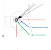
So perhaps this screen shot will illustrate succinctly what I am trying to figure out. The hole was created in the assembly. The blue annotation points to the cross hairs that showed up at the hole center when I first generated the drawing from the assembly, with the hole in its original position. Then I moved the hole - in the assembly. Then I reprojected the views - from the assembly. The callouts moved with it (black arrows), and the center mark crosshairs did not. What's going on with that is all I want to know.
The reason for moving the hole was that the entire part that is in hidden lines is what I decided to move a little bit to the left, and the way I had it drawn, it all worked wonderfully, moving the axis the mount holes were on, all of it... except these little center marking crosshairs when I generated the drawing. Seems odd.
1676726446391.png
 

DavidJ

Administrator
Staff member
Just did tests here - the centre marks moved with the hole when the drawing views were re-projected to pick up the change in assembly hole position on my test pieces (not as complex as yours)

Did you add all centres to the original, or just centre for the hole?

You can always 'add centres' again.

When I made a drawing view of your assembly, adding all centres picked up on the sheet metal part (as I found out by hiding each part and notice when the centre mark vanished) - that surprised me a bit - after I moved the assembly hole in side plate, centre didn't move with it because it was never associated with it. I speculate that if features that would warrant centres are coincident, insert centres stops after adding one centre mark.

If you want to be specific in such cases, you can isolate a part, then add centres, then 'show all parts'.
 

evandene

Member
Hello,

I moved a hole in an assembly, this hole is a feature of the assembly, not of the base part, as it must be set to fasten two assembly parts.

When I had the hole in its original position, the hold shows up correctly in the drawing I generate from the assembly. When I moved the hole, the new position is not updated in the drawing. Interestingly, the callout pointers for the drilling moved with the hole, the crosshairs for the dimensions I drew after re-projecting the views did not.

What am I missing here?
Most probably you changed the dimension manually in the drawing(overide). The consequences are that the association is lost with the 3D model.
In my company, persons will get fired instantly.
 

MikeHenry

Alibre Super User
You also need to save the source file (part or assembly) before re-loading the drawing for the drawing to update correctly. That requirement catches me all too often.
 

mmtech

Member
Thank you for these comments and taking the time. To my memory I did do the following before posting:
- re-saving, re-opening the model before re-opening the drawing.
- re-rendering with centermarks.

@DavidJ "isolate a part, then add centres, then 'show all parts'." this is in the assembly, correct?

@evandene will it override the center marks just by adding a dimension that comes off the existing information? I did not re-create any dimension values in the drawing.

What I found weird was that I could delete the dimensions, callouts, etc. if I felt there was duplication, and I could not delete the mis-located centermark. If it had disassociated from the underlying part, why couldn't I delete it? It was this that caused me to redraw the whole thing.
 

DavidJ

Administrator
Staff member
I was referring to the 2D DRAWING, that's the only place where you'll find an 'isolate' command - after all, your question was about drawings.

It would be much simpler if you included your problem drawing file.
 
Top