What's new

Need Help with Tapered Shaker Leg only using Loft

WoodWorks

Alibre Super User
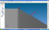
I have been creating a Shaker style tapered leg, with a length of square section at the top, using a loft for the tapered section, and an extrude for the square section at the top.

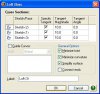
However, I have been trying to do the same type of leg using only the Loft command and have yet to succeed. I have attached a zip of an Alibre v10 Part file with the 3 sketch cross sections, and 4 guide curves. When I create the leg using just the 3 cross sections, there is a bulge along the tapered section. When I try to use the guide curves, it does not work.

Miles; I have been using your Square Twisted as inspiration and guidance. Maybe you can offer suggestions on how to use guide curves.

This is a simple example that I have been trying to solve before tackling more complicated models. There is little information and examples on how to do lofts with guide curves, and I am trying to add to that information.
 

Attachments

  • Shaker Leg Loft.zip
    14.2 KB · Views: 379

DavidJ

Administrator
Staff member
I've seen similar small bulges on a tapered part I made using a loft between cylindrical extrudes. The case I'm thinking of had a bulge that was only visible if zoomed right in, I only noticed the problem after exporting the model to FEA when it wouldn't mesh.

No idea why this happens - in my case I was able to use a revolve boss instead, though it took a bit more work.
 

NateLiquidGravity

Alibre Super User
You could eliminate the guided curves on your design if something like this is acceptable. A little bit of radius on the first edge and a slight bulge on the next. I was zoomed in quite a bit.


Note that this is not on your part. I made a similar shape that was much more exaggerated in size to see what was going on easier.

The following settings gave the best results on my test part. I think you may have to try different values for the tangent magnitude - I tried even numbers only for the test so you might get it closer to zero curve. A lower setting gave more bulge and a higher one gave me more bulge. I don't know if that is because the distance my profiles were apart was around 10.
 

Attachments

  • loft2.JPG
    loft2.JPG
    44.1 KB · Views: 326
  • loft.JPG
    loft.JPG
    27.4 KB · Views: 2,402

DavidJ

Administrator
Staff member
I do find some of these option settings in Alibre frustrating, I suspect they are very powerful but usually can't find a proper description of what they actually represent. What is 'tangent magnitude ' supposed to mean??
 

WoodWorks

Alibre Super User
I have found that the problem I am having with guide curves is that I am using a line, which is not continuous for the entire loft as I have a point on the shoulder sketch. If I use a Spline or an arc, it is a continuous curve that runs from end to end. However, neither will give me the sharp edge at the shoulder cross section. If a sharp transition is required in a loft, then the loft will need to be broken into multiple sections/features.

While I have come close (using some of the techniques posted here), the only way to get a true model with straight sides is to construct two lofts (tapered and straight), or a loft for the taper, and an extrude for the straight section. I think the most efficient method of constructing this leg is to create the 3 sketches as I have done, create the tapered loft, and then create an extrude from the Top Sketch with option of To Next to the tapered section of the leg.

I have found that a loft can be constructed between two or more sketches, or a face and one or more sketches (such as the face at the top of the taper). However, guide curves can only be constructed between two or more sketches and not from a face (you can construct a guide curve from a face, but it will not create a valid model if used). I can use Project to Sketch, and create another Sketch on the face at the top of the tapered section of the leg, and then create guide curves from the top of the tapered section to another sketch. If I create a loft from the top tapered face, and the Top Sketch, then some residual influence of the taper (no matter how slight) will still make it's presence felt.

I can also use 4 lines each (8 total) as guide curves in each of the two sections of the two part loft, but that is a bit redundant as a straight line would be the normal result between two sketches. Where the information learned from this example becomes worthwhile, is when the guide curves are more complex than straight lines. A guide curve from each corner with a setting of local, will control the shape of each edge of the leg. A single guide curve with a setting of Global, will control the shape of the entire cross section. I still need to experiment with the results of using the Tangent option for the guide curves.

I have attached a version with a lofted top (and very little bulge - zoom way in), and a second configuration that is an extrude. It has all 8 of the guide curves defined, and you can experiment using guide curves for two different lofts. The default configuration is the Loft, so those without configurations can still experiment with the loft configuration of the model. To use the guide curves for the straight section you will need to delete the current Straight Loft and construct a new one using the Projected Sketch and the Top Sketch.
 

Attachments

  • Shaker Leg Loft3.zip
    37 KB · Views: 367

indesign

Alibre Super User
Consider creating the leg a little longer than needed and then trimming the end off later. This way the small curve on the edge is not part of the problem.
 
Top