RCH_Projects
Alibre Super User
With little to no literature regarding failing results in Dynamics I wanted to start this thread. Time allowing I'll try to add symptoms and solutions for issues I've encountered.
My applications are not typical so a user may or may not encounter any particular issue. Other issues have a greater potential to be encountered and are totally vexing without some insights.
Having posted the issue herein elsewhere I feel obligated to post this solution promptly.
More modest simulations are probably not subject to many of these issues.
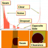
On another post I complained that "On Smooth Surface single point contact a "seam" and/or angular relationship can trigger unusable chart results or cascade constraint failures."
Extending trials with "extreme" settings resolve the issue.
Although no explanation for the section of "noisy" results in graphing is available and the sharp dropout of data at the transition point remains, the effect is trivial in the overall analysis (as I am not an FEA user).
Some background on the simulation is a rotating shaft with friction coefficient set at .999.
This permits me to graph the maximum force in the shaft and components in a given simulation.
The high friction slows or even stops rotation without "bumping" the rotation with an input torque when rotation falls below or exceeds a designated RPM (input[115] rpm lbf ft s/deg).
The rotation is monitored through an excel spreadsheet and a bump value returned to Dynamics to generate a steady rotation.
Unlimited rotation appears to create problems in an assembly such as mine where a larger number or special interactions create a need for more intermediate steps.
This also creates a more meaningful chart without bunching values together as speed picks up during simulation with low friction.
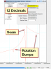
Using position tolerance with 12 decimal places creates a very smooth data flow. The noted drops in force are due to a rotation bump as speed drops and can be accounted for.
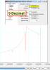
A position tolerance of 9 runs faster with some detail loss.
The simulation is extremely slow in the noisy section but resumes a brisk pace when clear of the quirky area.
The noisy section is not extraordinary otherwise.
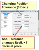
Assembly and Bond tolerance do not appear to influence simulation (FEA settings?) and I keep the values neutral.
The simulation also uses an animation frame rate Time of ".005", Integration Step "variable" with Steps per frame of "8" and the "Kutta-Merson" integrator.
Overlap Tolerance and Significant Digits can be problematic if too high or low (for a later post). The values I use are suitable for the assembly used.
Orientation has not been significant within the values I've tested but I'll review and post any observation down the road.
My applications are not typical so a user may or may not encounter any particular issue. Other issues have a greater potential to be encountered and are totally vexing without some insights.
Having posted the issue herein elsewhere I feel obligated to post this solution promptly.
More modest simulations are probably not subject to many of these issues.
On another post I complained that "On Smooth Surface single point contact a "seam" and/or angular relationship can trigger unusable chart results or cascade constraint failures."
Extending trials with "extreme" settings resolve the issue.
Although no explanation for the section of "noisy" results in graphing is available and the sharp dropout of data at the transition point remains, the effect is trivial in the overall analysis (as I am not an FEA user).
Some background on the simulation is a rotating shaft with friction coefficient set at .999.
This permits me to graph the maximum force in the shaft and components in a given simulation.
The high friction slows or even stops rotation without "bumping" the rotation with an input torque when rotation falls below or exceeds a designated RPM (input[115] rpm lbf ft s/deg).
The rotation is monitored through an excel spreadsheet and a bump value returned to Dynamics to generate a steady rotation.
Unlimited rotation appears to create problems in an assembly such as mine where a larger number or special interactions create a need for more intermediate steps.
This also creates a more meaningful chart without bunching values together as speed picks up during simulation with low friction.
Using position tolerance with 12 decimal places creates a very smooth data flow. The noted drops in force are due to a rotation bump as speed drops and can be accounted for.
A position tolerance of 9 runs faster with some detail loss.
The simulation is extremely slow in the noisy section but resumes a brisk pace when clear of the quirky area.
The noisy section is not extraordinary otherwise.
Assembly and Bond tolerance do not appear to influence simulation (FEA settings?) and I keep the values neutral.
The simulation also uses an animation frame rate Time of ".005", Integration Step "variable" with Steps per frame of "8" and the "Kutta-Merson" integrator.
Overlap Tolerance and Significant Digits can be problematic if too high or low (for a later post). The values I use are suitable for the assembly used.
Orientation has not been significant within the values I've tested but I'll review and post any observation down the road.